SLLA593 August 2022 TUSB211 , TUSB212 , TUSB216 , TUSB216I , TUSB217A
2.1 Host Mode Test Procedure
It is important to start the test procedure with all connections to the TUSB21XX device disconnected and no test packets being sent from the host. Doing so will ensure high-speed signal compensation is active throughout the test. The host mode test procedure is as follows:
- Connect TUSB21XX input to host (test packet source).
- Toggle RSTN (reset) on TUSB21XX.
- Connect TUSB21XX output to oscilloscope/measurement tool.
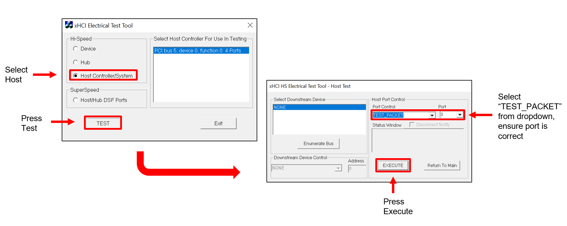
- Send high-speed test packets via xHCI Electrical Test Tool (Figure 2-2).
 Figure 2-2 Host Mode Testing Software
Configuration
Figure 2-2 Host Mode Testing Software
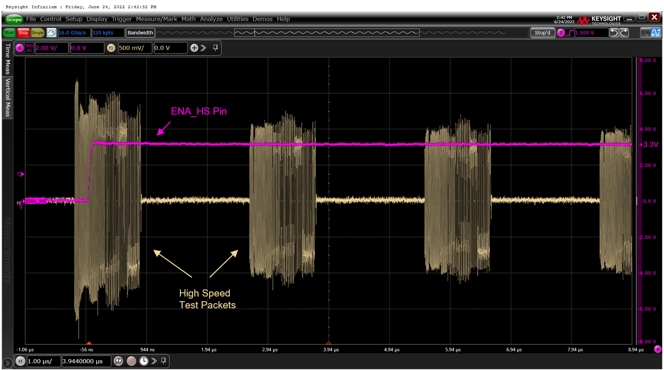
ConfigurationOnce test packets have been sent via software, the scope output and status flags should be observed as below. The high-speed enable (ENA_HS) flag switches high during the first test packet and remains that way for the duration of testing (Figure 2-3).
 Figure 2-3 Host Mode Enable High-Speed
(ENA_HS) Status Flag
Figure 2-3 Host Mode Enable High-Speed
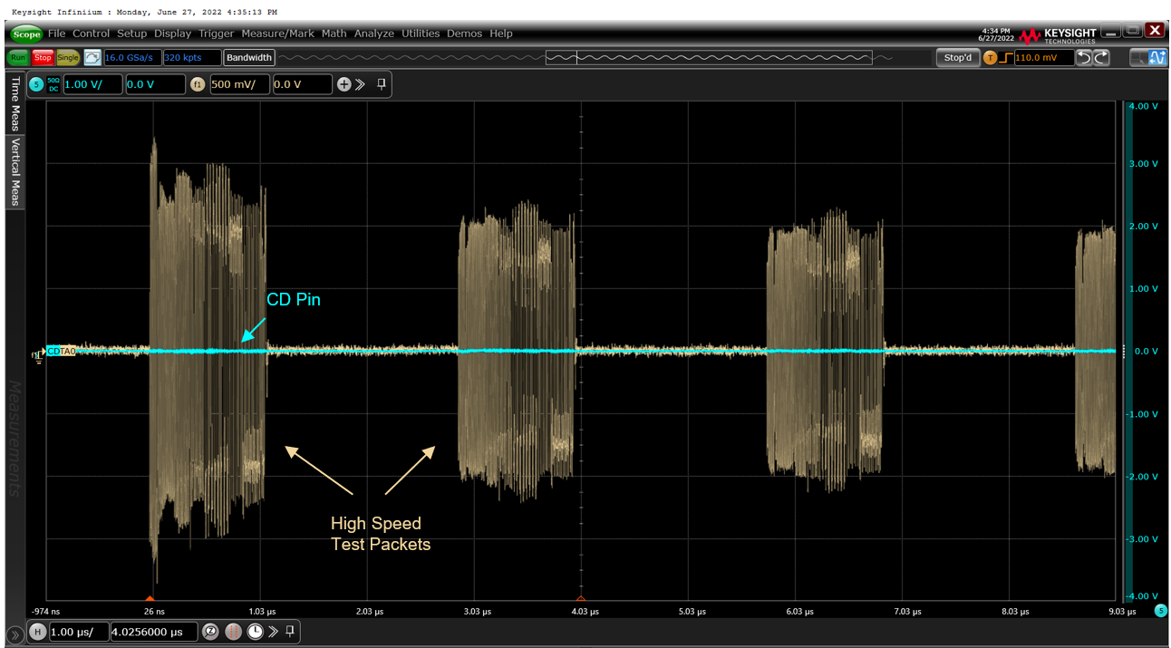
(ENA_HS) Status FlagThe connection-detected (CD) flag remains low during all steps of testing (Figure 2-4).
 Figure 2-4 Host Mode Connection-Detected
(CD) Status Flag