SLLU314 March 2020 ISO1044
7.1 Protection Configurations
The EVM also has footprints for various protection schemes to enhance robustness for extreme system level EMC requirements. Figure 7 summarizes these options
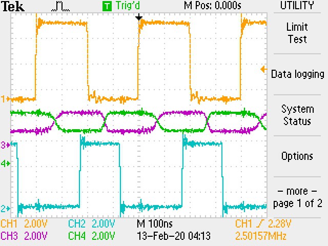
Figure 7 shows typical input and output waveforms of the EVM for a 5-Mbps signal. TXD is shown as Channel 1, the CAN bus is shown as Channel 2, Channel 3 and RXD is shown as Channel 4.
 Figure 7. Typical Input and Output Waveforms
 | Configuration | Footprint Reference | Use Case | Population and Description |
|---|---|---|---|
| Series resistors or common mode choke | R1/R5 or L1 | Direct CAN transceiver to bus connection | R1 and R5 populated with 0Ω |
| Series resistance protection, CAN transceiver to bus connection | R1 and R14 populated with MELF resistor as necessary for harsh EMC environment | ||
| CM choke (bus filter) | L1 populated with CM choke to filter noise as necessary for harsh EMC environment (Default Population) | ||
| Bus filtering caps and transient protection | C8/C9 | Bus Filter | Filter noise as necessary for harsh EMC environment. Use filter caps in combination with L1 CM choke |
| C8/C9 or D1 | Transient and ESD protection | To add extra protection for system level transients and ESD protection. TVS diode population option via D1 footprint or varistor population through C2/C7 footprint. |