SLLU327 May   2020 TUSB217A


  1.   Trademarks
  2. 1TUSB217AEVM-BC
  3. 2TUSB217AEVM-BC Board Description
  4. 3TUSB217AEVM-BC Kit Contents
  5. 4EVM Configuration
    1. 4.1 Setting EVM Jumpers
    2. 4.2 Selecting Configuration Levels
    3. 4.3 Battery Charging Functions of TUSB217A
      1. 4.3.1 Automatic DCP/CDP Test Setup
      2. 4.3.2 Manual DCP/CDP Test Setup
  6. 5EVM Operation
  7. 6TUSB217AEVM-BC Schematics
  8. 7TUSB217AEVM-BC Bill of Materials (BOM)

TUSB217AEVM-BC Board Description

The TUSB217AEVM-BC (see Figure 2-1) is designed to provide easy evaluation of the TUSB217A device. It is also meant to serve as a reference design to show a practical example of how to use the device in a mass-production system.
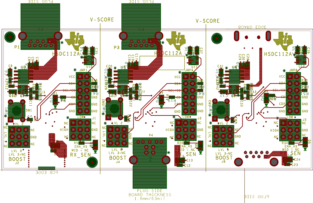
GUID-20210224-CA0I-LFCN-CR0F-JZ77MCJKJ6V2-low.gif Figure 2-1 TUSB217AEVM-BC