SLLU355 October 2022 TCAN1046A-Q1 , TCAN1046AV-Q1
- TCAN1046A/V Evaluation Module
- Trademarks
- 1Introduction
-
2EVM Setup and Operation
- 2.1
Overview and Basic Operation Settings
- 2.1.1 VCC Power Supply (J6 and J21)
- 2.1.2 I/O Power Supply VIO (J17)
- 2.1.3 Transmit and Receive Connections(J11 and J22)
- 2.1.4 TXD Inputs (J11/J22, TP13 and TP14/TP29 and TP31)
- 2.1.5 RXD Outputs (J11/J22, TP15 and TP16/TP30 and TP34)
- 2.1.6 STBY inputs (J12 and J13/J24 and J25, TP10 and TP12/TP32 and TP33)
- 2.1.7 Bus Observation (J3 or J8/J14 or J19)
- 2.1.8 Bus protection
- 2.2 Using CAN Bus Load, Termination, and Protection Configurations
- 2.3 Using Customer Installable I/O Options for Current Limiting, Pullup and Pulldown, Noise Filtering
- 2.1
Overview and Basic Operation Settings
- 3CAN EVM Configuration for TCAN1046A and TCAN1046AV
1.2 CAN EVM
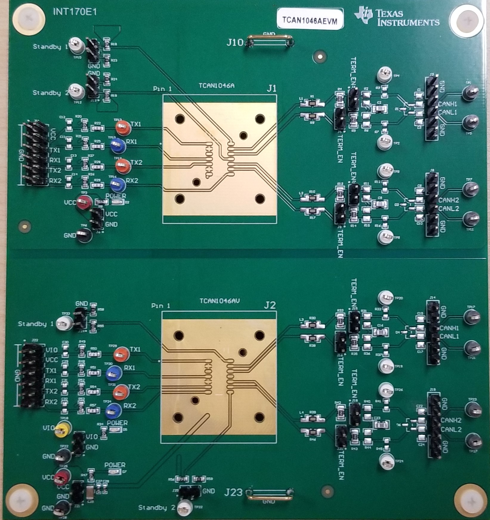
The TCAN1046A/V EVM has simple connections to all necessary pins of the CAN transceiver device, and jumpers where necessary to provide flexibility for device pin and CAN bus configuration. There are test points (loops) for all main points where probing is necessary for evaluation such as GND, VCC, TXD, RXD, CANH, CANL, STBY, and VIO. The EVM supports many options for CAN bus configuration. It is pre-configured with two 120-Ω resistors that are connected on the bus via jumpers: a single resistor is used with the EVM as a terminated line end (CAN is defined for 120-Ω impedance twisted pair cable) or both resistors in parallel for electrical measurements representing the 60-Ω load the transceiver “sees” in a properly terminated network (that is, 120-Ω termination resistors at both ends of the cable). The bus also has termination of two 60-Ω resistors in series with a 4.7nF capacitor to GND at the midpoint, all soldered down. This gives the option to test the other typical termination network on CAN buses.
Figure 1-1 shows the EVM board image.
 Figure 1-1 EVM PC
Board
Figure 1-1 EVM PC
BoardFigure 1-2 shows the EVM schematic.