SLOA198A September 2014 – December 2021 DRV2665 , DRV2667 , DRV2700 , DRV8662
- Trademarks
- 1 Boost Converter Basics
- 2 DRV8662, DRV2700, DRV2665, and DRV2667 Boost Converter
- 3 Configuring the Boost Converter
- 4 Boost Converter Output Voltage
- 5 Calculating the Load Current
- 6 Selecting an Inductor
- 7 Calculate the Maximum Boost Current
- 8 Output Capacitor Selection
- 9 Input Capacitor Selection
- 10PCB Layout
- 11Examples
- 12Revision History
11.2.2 Configure the Inductor Current
The Piezo load requires approximately 1.88 mA of average current based on the following equation:
| Piezo Actuator Current Requirements (Approximate) | |
|---|---|
| Iout_max = 2π × Cactuator × Vboost × ƒin_max | Iout_max = 1.884956 mA Maximum required amplifier current (estimate) |
 | Ibat_max = 139.626 mA Maximum VBAT current |
This means that the inductor current limit (REXT) needs to be sufficiently large to support 1.88 mA.
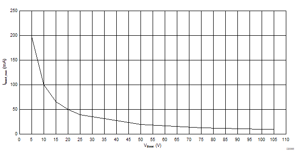
The DRV2667EVM-CT inductor is already fixed, but from here forward you may choose a different inductor that fits your load requirements. The maximum boost current with 80 Vp boost voltage is 12.4 mA, based on the 3.3-µH /1.1-A TDK inductor selected using the following equations:
| Boost Converter Current Capacity (Approximate) | |||||||||
|---|---|---|---|---|---|---|---|---|---|
 |
D = 0.978 Estimated duty cycle at maximum frequency |
||||||||
 |
Iboost_max = 12.400 mA Maximum boost output current estimate |
||||||||
 |
Vboost (V) | IOUT (mA) | |||||||
| 25 | 39.68 | ||||||||
| 50 | 19.84 | ||||||||
| 75 | 13.23 | ||||||||
| 100 | 9.92 | ||||||||