SLOA292 May 2020 TAS5760LD
4.1 Terminations Resistor Design and Simulation
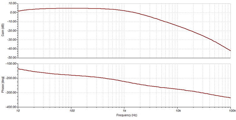
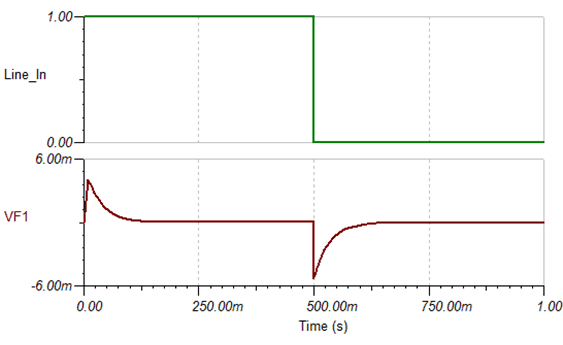
First, change the output impedance R5 from 1 k Ω to 270 Ω. The frequency response stays flat from 20Hz to 200Hz. This application report uses TINA to simulate the SOC bigger transient via step response method. VF1 is the Line driver output. Figure 9 shows the transient can be improved to around -6mV.
 Figure 7. Subwoofer Line Driver Stereo to Mono Design With Output Impedance 270Ω Resistor
  Figure 8. Frequency Response of Typical Subwoofer Line Driver Stereo to Mono Circuit
  Figure 9. Step Response of Typical Subwoofer Line Driver Stereo to Mono Circuit