SLOU432B December 2015 – December 2021 DRV2625
4.7 Analog Input
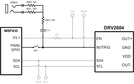
 Figure 4-5 Analog Input
The analog input accepts an analog signal to control the envelope of the output waveform.
Use the following steps to use analog input mode:
- Apply an analog signal (not PWM) to the AUDIO jack on the left side of the board. The tip of the inserted male 3.5 mm jack is applied to the IN/TRIG pin of the DRV2625. See Figure 4-5.
- Enter Additional Hardware Modes.
- Select Mode 5 (00101’b) using the increment mode button (+).
- In Mode 5, choose button B1–B4, depending on the actuator and input coupling.
- B1 – AC Coupling – ERM
- B2 – DC Coupling – ERM
- B3 – AC Coupling – LRA
- B4 – DC Coupling – LRA
- Enable the analog input signal.