SLUA475 November 2016 BQ2060A , BQ20Z80 , BQ40Z50-R1 , BQ40Z50-R2 , BQ40Z60 , BQ78350-R1 , BQ78350-R1A
1.2.4.1 Example 1
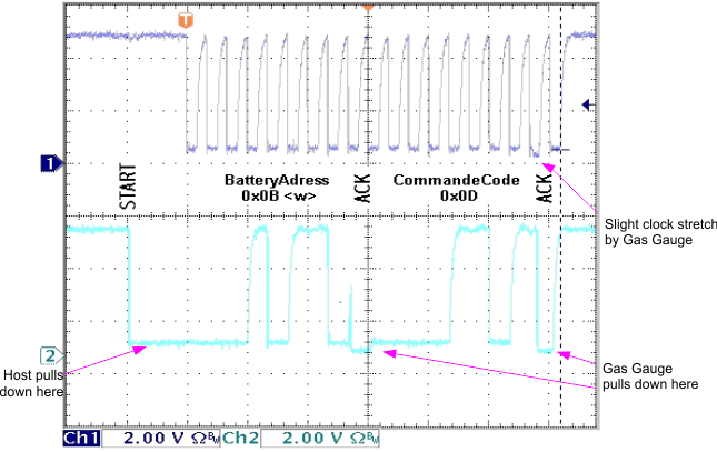
 Figure 5. Example 1
 Example 1 is shown in Figure 5. Notice that one can actually determine which device is pulling down on the bus at any given time. The zero threshold for the fuel gauge is at a lower voltage than the zero threshold for the host. The oscilloscope is an extremely useful tool when debugging to determine which device is in control of the bus. The reason this works is due to the current flowing through series protection resistors on the bus. The zero threshold is slightly different depending on which side of these series resistors the scope probe is connected with reference to ground.
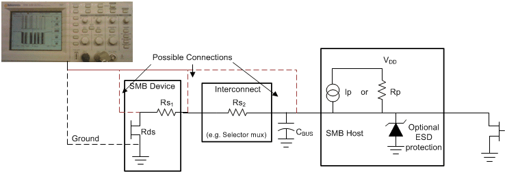
Figure 6 is a modified picture showing different connection points for an oscilloscope probe. Each point has a different zero level voltage in reference to ground. The difference also varies depending on the resistors used in the circuit. This original picture was derived from the SMBus specification.
 Figure 6. Different Connection Points for an Oscilloscope Trace