SLUA749A July 2015 – May 2016 BQ76920 , BQ76930 , BQ76940
2 Cell Count
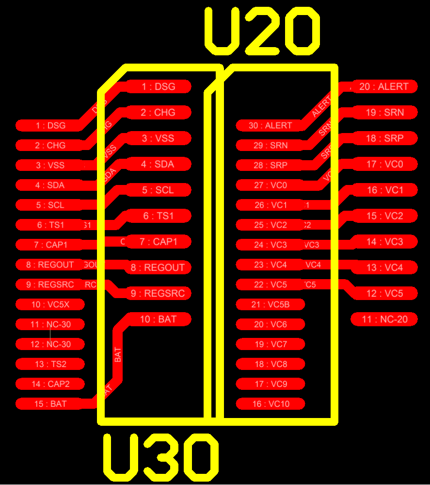
The bq769x0 family devices use a common register architecture to allow a host implementation to easily move across different cell count configurations. It would seem attractive to make a single board which could support any cell count supported by the AFE family. From the controller and firmware standpoint this should work well, however, there are hardware considerations which may make this unattractive. One is the inefficiency of having the board space for 15 cells when fewer cells are actually used. A second consideration is the package pitch difference between the bq76920 (0.65 mm) and the bq76930 and bq76940 (0.5 mm). A common footprint might be constructed with offset patterns similar to Figure 1, but this may have complications in component placement and routing. A third is the circuit structure differences resulting from the architecture of the family devices, details of this are described in following sections. A common board design between the bq76930 and bq76940 may be more practical; this was done on the bq76930 and bq76940 EVM boards. The cell count will generally indicate the device to use, see the datasheet for supported cell counts. In cases where there is an overlap in the cell count supported between devices such as 9 or 10 cells the selection might be based on the lower cost part or the desirability of an extra temperature sensor.
 Figure 1. Common Footprint Concept