SLUA888 May 2018 TPS53622 , TPS53659 , TPS53679 , TPS53681
-
NVM Programming for VR13 Power Controllers
- Trademarks
- 1 Introduction
- 2 Technical Overview
- 3
Use of TI Programming Tools
- 3.1
Fusion Digital Power Designer
- 3.1.1 Build and Export a System (.tifsp) File
- 3.1.2 View a Project File or System File Offline
- 3.1.3 Import a Project File to a Single Online Device
- 3.1.4 Import a System File to an Online System
- 3.1.5 Export CSV Script for Third Party Tools
- 3.1.6 Compare Two Project Files
- 3.1.7 Build a System File from Existing Project Files
- 3.2 Fusion Manufacturing Tool
- 3.3 TI Programming Board
- 3.1
Fusion Digital Power Designer
3.1.7 Build a System File from Existing Project Files
New projects often share components with previous projects. With the Fusion Digital Power Designer software, designers can assemble a System (.tifsp) file using controller devices from existing Project files or System files. Individual projects must not be modified offline. However you can safely assemble existing Project files into a System file when the software operates in offline mode.
- Start Fusion Digital Power Designer in offline mode.
- Open an existing System file.
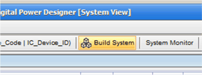
- From the System View, select Build System.
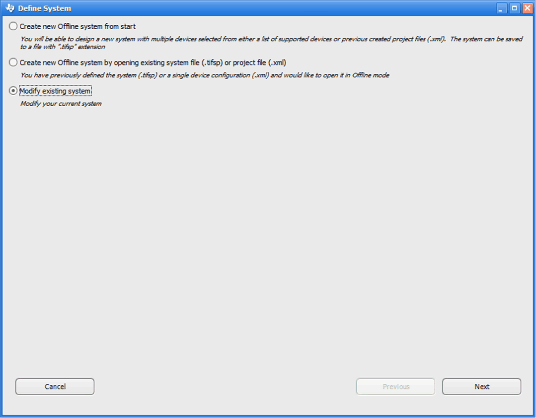
- From the Define System window, select Modify an existing system.
- Click Next.
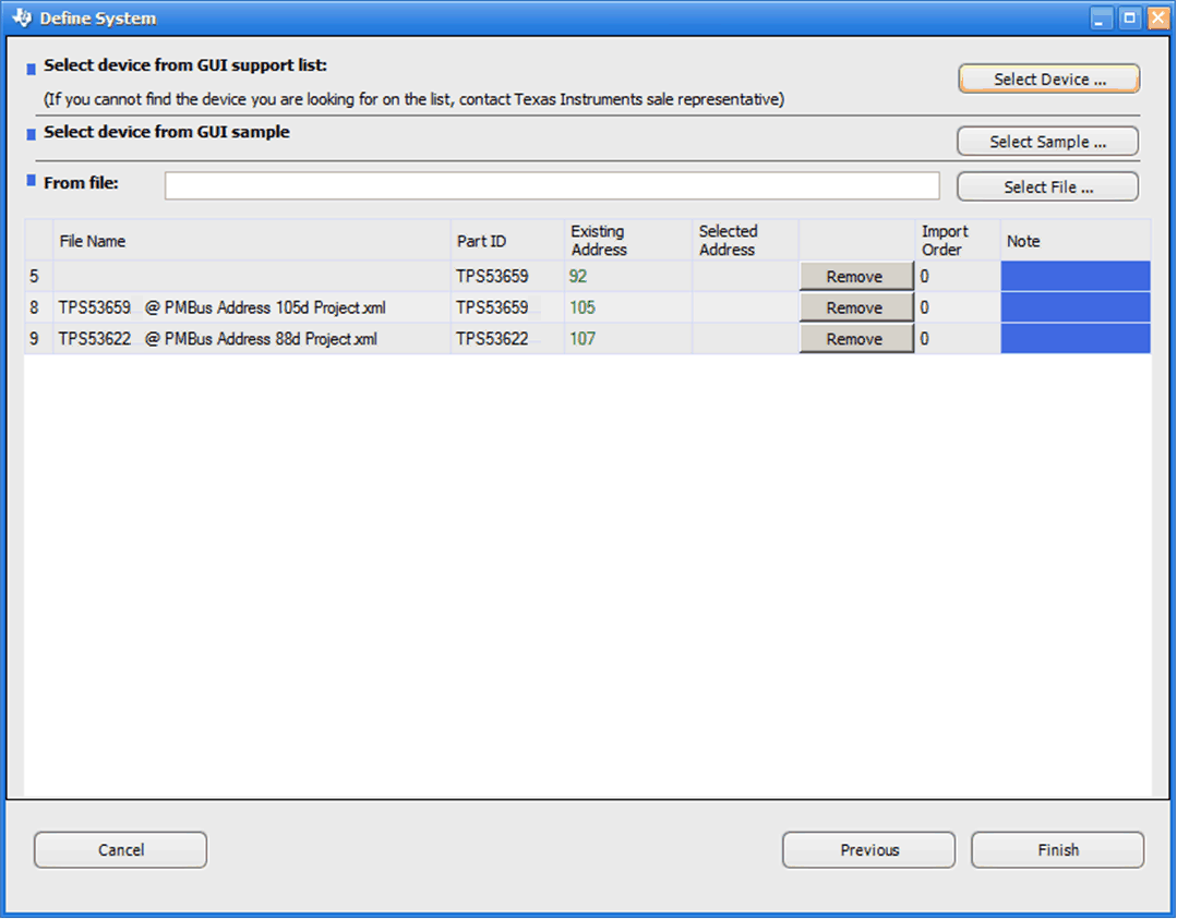
- The software displays the selected Project file names, the components and the addresses.
- Click Remove to delete a device if needed.
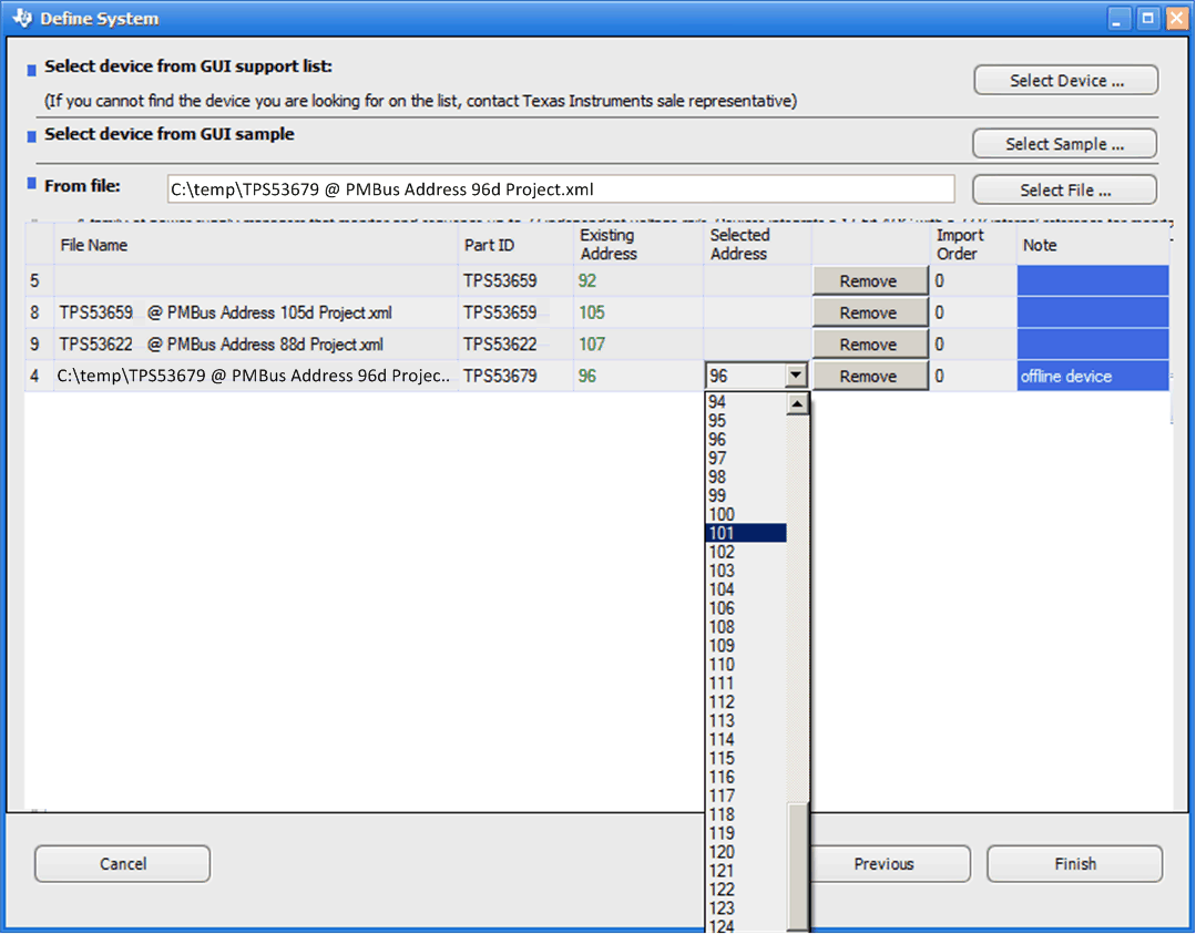
- To add a Project file, click Select File.
- Browse to the Project file.
- Update the PMBus address if necessary by clicking in the Selected Addresses cell.
- Repeat steps 8 through 10 to add more Project files to the system.
- Click Finish.
 Figure 33. Build System
 Figure 34. Modify Existing System
 Figure 35. Existing Project File Devices
 Figure 36. Add a Project File to a System File