SLUAA12 March 2020 TPS53681
- Selection Considerations for Output Capacitors of Multiphase Voltage Regulators Part 1
1 Introduction
High-performance microprocessors require low voltage and high current voltage regulator modules(VRM). The large supply current not only poses a stringent challenge on efficiency, but also heavily burdens the transient response. To ensure fast load transient, output capacitors and output impedance should be optimized.
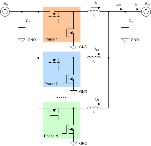
In multiphase voltage regulators based on interleaved buck topology, the inductor selection of L is decided by current ripple, reflecting trade-off between inductor volume and power losses. Then, the output capacitance Co is based on both steady-state ripple and load transient specification(undershoot vud and overshoot vov). In most of the cases, not steady-state ripple but load transient of output voltage is the major limiting factor for output capacitance selection.
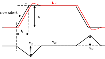
For a buck converter, some equations were provided to calculate output capacitance based on load transient, but they are under perfectly ideal cases, without taking specific load step characteristics, loop response influence, controller limitations and multiphase features into consideration. Actually, shown in Figure 2, load step characteristics like slew rate k, amplitude A, and repetitive rate (or called frequency) will highly decide how the controller responses to the load transient.
 Figure 1. Multiphase Voltage Regulator Diagram
  Figure 2. Undershoot and Overshoot of Load Transient
 When closed loop adjusts automatically, it may go into saturation as equivalent duty cycle goes to zero or maximum, with load disturbance.
Whether saturated or not, the control loop will have a key impact on load transient performance. With analysis of frequency domain bode plot, as well as system type and bandwidth, load transient with unsaturated loop can be completely described by a linear system transfer function. While the control loop is saturated, load transient should be taken over by physics, including controller limitations, and parameters like inductance and capacitance.
To clearly research on how TI controller with D-CAP+™ control would respond in non-Intel application, analysis will be done by assuming DC load-line(DCLL)=0, and dynamic phase shedding(DPS) and non-linear features(like OSR) disabled. USR feature is automatically inactive when DPS is disabled.