SLUAA80 November 2020 TPS40322
3.2 Software GUI Setup
Utilize the bqStudio GUI for read/write the I2C commands to I2C slave device. Use the following procedure to set up the bqStudio GUI to control the TPL0102-100EVM and adjust as a variable resistor. Figure 3-5 second (fourth) Figure 3-6
- Open BqStudio,
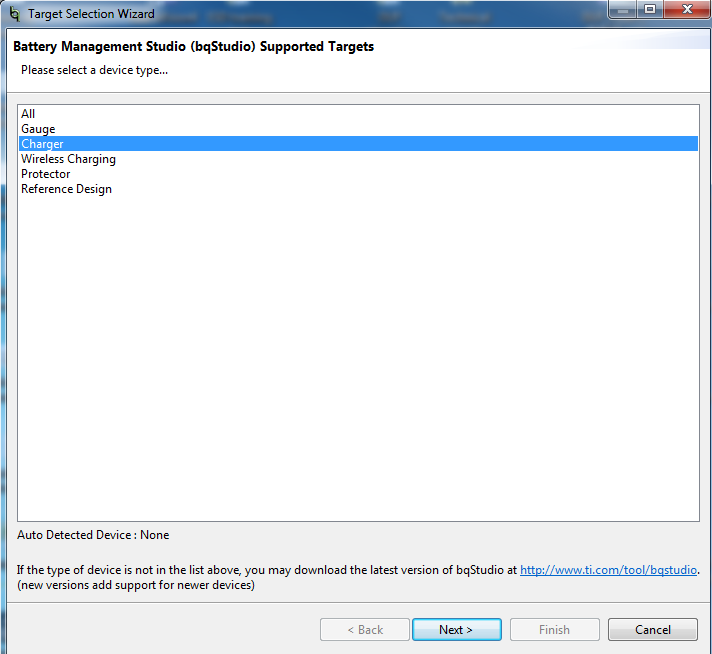
select Charger, and click the Next button
 Figure 3-3 Charger Device Type.
 - Select the
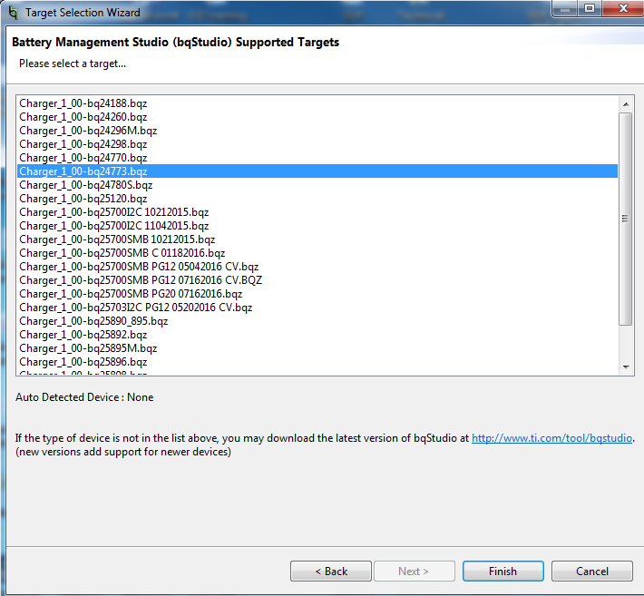
bq24773.bqz target and click the
Finish button
 Figure 3-4 bq24773.bqz Target.
 - Select the
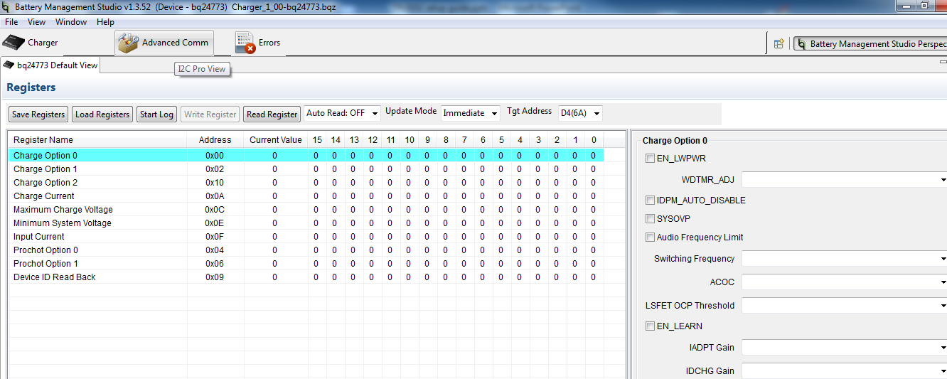
Advanced Comm tab
 Figure 3-5 Advanced Comm tab.
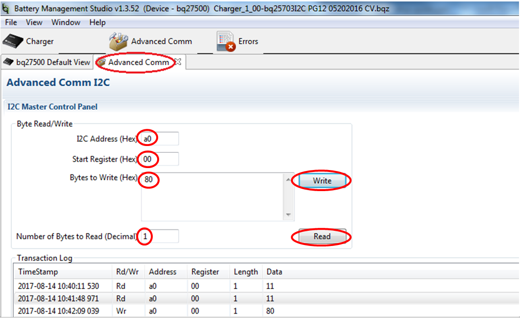
 - Read/Write I2C command to
TPL0102-100 EVM
illustrates using the Advanced Comm tab to set the device address to 0xA0h and read/write 1 byte data from and to the register 0x00h for accessing the Wiper Resistance Register of Potentiometer A.
 Figure 3-6 Byte Read/Write Settings.