SLUAAC5 August 2021 UCC28700 , UCC28701 , UCC28702 , UCC28703 , UCC28704 , UCC28710 , UCC28711 , UCC28712 , UCC28713 , UCC28720 , UCC28722 , UCC28730 , UCC28740 , UCC28742 , UCC28910 , UCC28911
- Trademarks
- 1 Introduction
- 2 Brief Review of DCM FM, AM, FM Flyback Control Law
- 3 Input (VIN) and Output (VOUT) Voltage Sensing for UVLO and OVP Fault Protection
- 4 Input Under Voltage Lockout (UVLO) Protection
- 5 Output Overvoltage (OVP) Protection
- 6 Not Recognizing a UVLO or OVP Fault
- 7 Separate Bias Supply Startup Issue and Resolution
- 8 Not Having a Clean Aux Winding Signal
- 9 Removing Aux Winding Ringing to Resolve False Triggering of OVP and UVLO Faults
- 10Noise on CS Pin Tripping Over Current Protection (OCP)
- 11Summary
- 12References
3 Input (VIN) and Output (VOUT) Voltage Sensing for UVLO and OVP Fault Protection
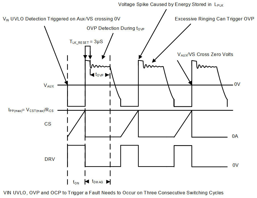
VIN and VOUT are sensed and measured across the auxiliary winding (VAUX) that is used to provide power to the flyback controller (U1) while the transformer is being energized. Figure 3-1 shows the switching wave form of DCM flyback converter operating near critical conduction. In this figure DRV is the logic level of the flyback controllers gate driver and CS is the voltage measured across the current sense resistor (RCS). When the transformer is being energized during the flyback FETs (QA) on-time (tON) VIN can be measured directly across VAUX. Refer to Equation 1, Figure 1-1, and Figure 3-1 for details.
 Figure 3-1 Aux, CS,
and DRV Signals at Max Load Minimum Line Voltage
Figure 3-1 Aux, CS,
and DRV Signals at Max Load Minimum Line VoltageThe flyback controller can sense VOUT while the transformer is delivering energy after the flyback converters transformer leakage spike that occurs during the TLK_RESET time period has dissipated during tDMAG. Refer to Equation 2 and Figure 1-1 for details.
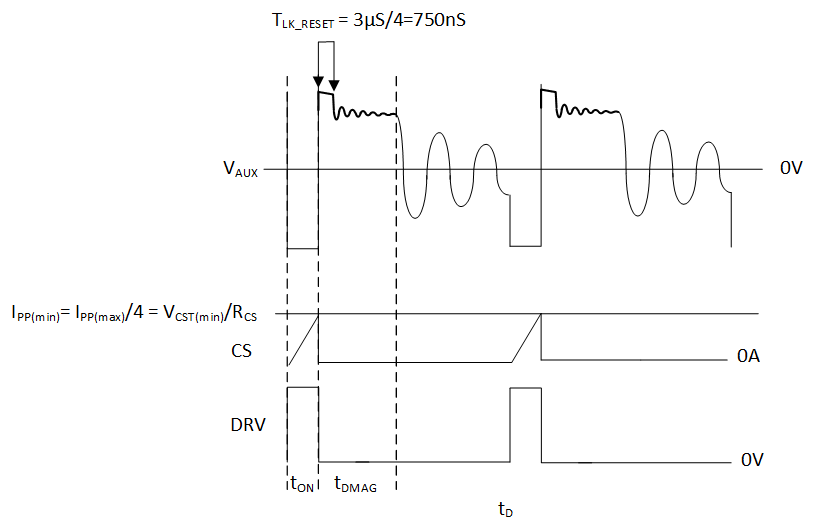
To prevent false measurements of VOUT the flyback controllers discussed in this paper have a leading edge blanking circuit. The controllers do not sense VOUT during pre-programed blanking time (TLK_RESET). TLK_RESET moves with loading. For example, at full load, the UCC28704 controller will not sense VOUT for 3 us (TLK_RESET). When operating in the AM band to control the duty cycle, the transformer primary peak current adjusts linearly from IPP to IPP/4 to control the duty cycle. When the UCC28704 is operating in the AM band TLK_RESET will be adjusted from 3 µs down to 750 ns as the primary-peak current decreases. When this occurs the flyback converter will go deeper into DCM operation. Refer to Figure 3-2 for details. Please note for this aux winding to sense the VOUT correctly requires the aux winding signal to be as clean as possible between the end of TLK_RESET and the end of tDMAG. This will be discussed in greater detail later in this application note.
 Figure 3-2 VAUX, CS, and DRV While the Flyback Operating Deep into DCM
Operation