SLUAAD0 September 2021 UCC28064A
- Trademarks
- 1Introduction
- 2Normal Theory of Multi Phases Control UCC28070 and UCC28064A Operation
- 3Achieving Adjustable Phase Control Operation with UCC28064A
-
4Achieving Multi Phases Control
Operation
- 4.1 Disable Feedback of Secondary (Connecting VSENSE and VREF Directly)
- 4.2 Disable Feedback of Secondary (Connecting VSENSE and VREF with Diode)
- 4.3 External 4 Multi-phase Mode Control Circuit of UCC28064A
- 4.4 Detail Operating for External Paralleling Two-Power Stages Control Circuit of UCC28064A
- 4.5 Test result for External Paralleling two power stages control circuit of UCC28064A
- 5Summary
- 6References
4.5 Test result for External Paralleling two power stages control circuit of UCC28064A
Figure 4-4 shows setting external circuit components value for optimizing 4-phase control with UCC28064A (Primary) and UCC28064A (Secondary). Testing power rating is PIN 1.5 kW and VINAC range is from 90 VAC to 264 VAC
* Adjustable voltage range 3.0V ~5V in the Blue square dotted line
Table 4-1 shows measuring current level value of load sharing multi- phase operating depends on input power rating conditions.
| Input Power(W) | 100W | 300W | 500W | 800W | 1000W | 1500W |
|---|---|---|---|---|---|---|
| Output Current (A) | 0.244 | 0.744 | 1.243 | 1.986 | 2.484 | 3.75 |
| Primary Output Diode Current(A) | 0.134 | 0.373 | 0.619 | 0.99 | 1.243 | 1.85 |
| Secondary Output Diode Current (A) | 0.11 | 0.371 | 0.623 | 0.996 | 1.241 | 1.9 |
| Load Share Regulation (%) | 9.84% | 0.27% | 0.4% | 0.3% | 0.08% | 1.33% |
Figure 4-5 waveforms show how well the paralleled TM PFC stages shared currents at different power levels.
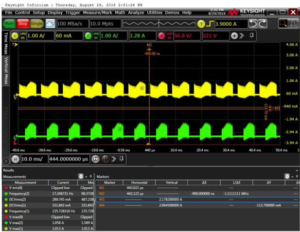 Figure 4-5 Waveform of
Multi-operating (100W)
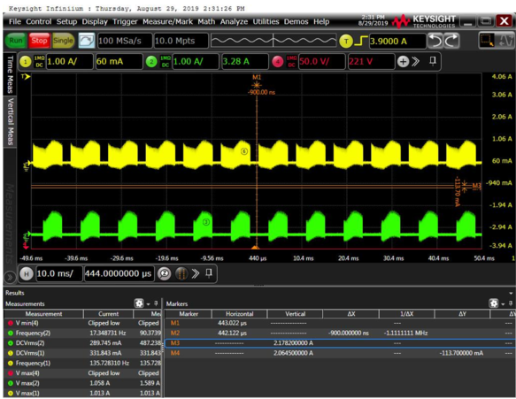 Figure 4-7 Waveform of
Multi-operating (500W)
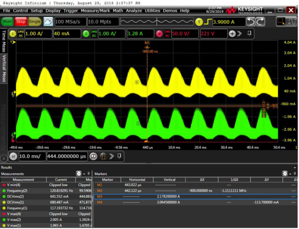 Figure 4-9 Waveform of
Multi-operating (1000W)
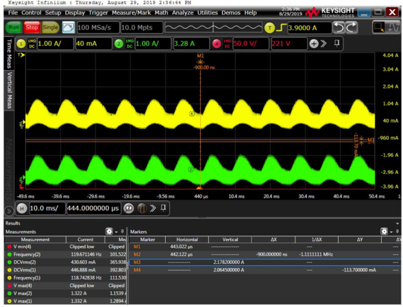 Figure 4-6 Waveform of Multi-operating (300W)
 Figure 4-8 Waveform of
Multi-operating (800W)
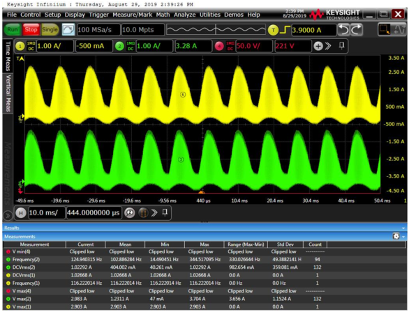 Figure 4-10 Waveform of
Multi-operating (1500W)
Figure 4-10 Waveform of
Multi-operating (1500W)Figure 4-11 shows how well the paralleled TM Interleaved PFC boost stages share current from a 100 W to 1500W loading.