SLUAAF8 October 2021 BQ24707 , BQ24707A , BQ24725A , BQ24735 , BQ24770 , BQ24780S , BQ24800 , BQ25700A , BQ25708 , BQ25710 , BQ25720 , BQ25730 , BQ28Z610-R1 , BQ4050 , BQ40Z50 , BQ40Z50-R1 , BQ40Z50-R2 , BQ40Z80
1 Introduction
Including only the gauge and charger reduces cost and size of simple BMS systems. The battery gauge replaces the functionality of the host MCU for a conventional system. Most standard battery systems would also use an MCU to communicate with other ICs, this increases the flexibility of the BMS, but also increases the BOM and cost. Using the battery gauge as the host is best for applications that are fairly simple and only require a State of Charge (SOC) readout with LEDs, safety protections, and passive cell balancing.
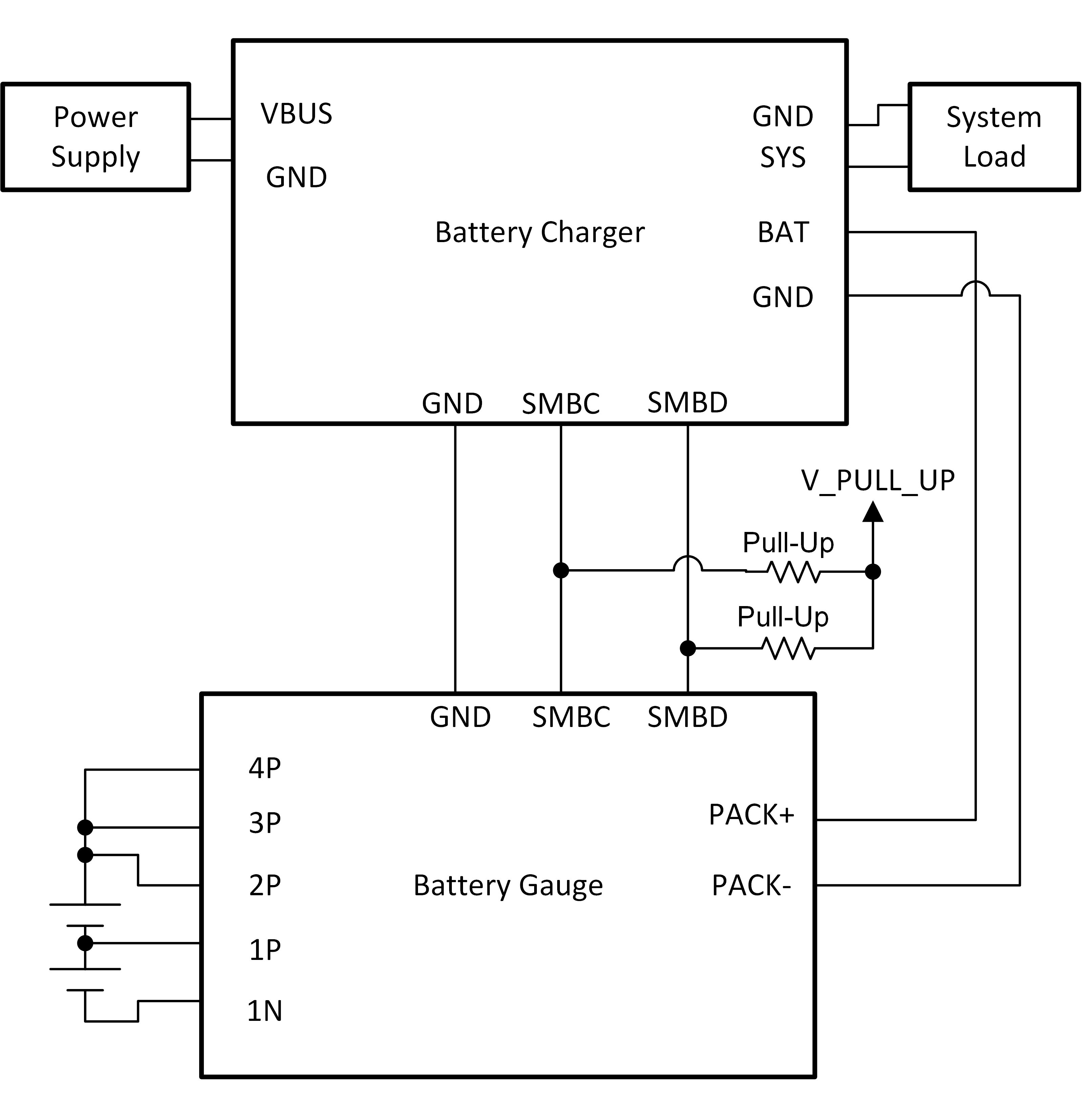
A power supply capable of supplying high enough current and voltage to charge the batteries is required. A load capable of discharging the batteries at a rate between C/5 and C/10 through the SYS pin on the charger is another requirement. The data line (SMBD), clock line (SMBC), and GND are the needed between the gauge and charger for communication. The power connections required are PACK– to GND, then PACK+ to BAT.
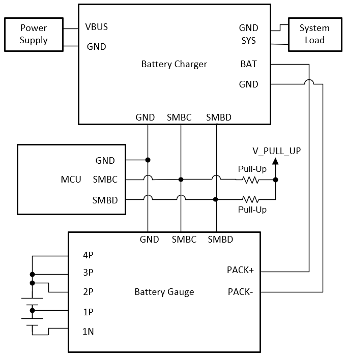
A conventional BMS with MCU controls the charger from the information read from the gauge along with other peripherals, compared to the smart battery system connections which do not include an MCU. The MCU for the conventional system reads the ChargingVoltage() and ChargingCurrent() from the gauge to then program the charger, or perform its own modifications to the charge profile before programming the charger.
 Figure 1-1 Conventional BMS Configuration Figure 1-1 Conventional BMS Configuration |  Figure 1-2 Smart Battery System Figure 1-2 Smart Battery System |