SLUAAF9 September 2021 UCC28782
- Trademarks
- 1 Initial Board Visual Inspection and Start-up Check
- 2 Typical System Operating Waveforms
- 3Typical System Protection Waveforms
- 4Common Issues and Solutions
- 5References
4.3.3 SR MOSFET Vds Voltage Overstress Due to PWMH Partial Turn On At Load Transition
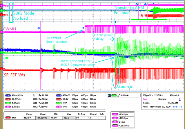
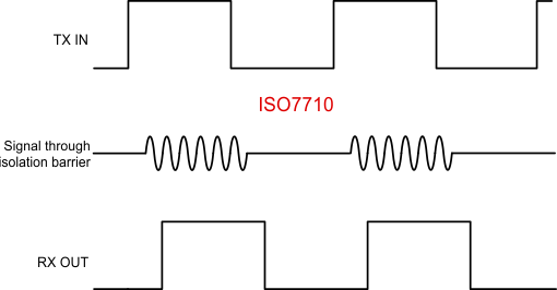
This could be caused by not correctly selected the isolator driver. When power stage running at no load, long burst off time will let isolator VCC drop to lower than UVLO. Once heavy load happens on output, controller will transfer to AAM mode, and PWMH enabled, but isolator driver cannot immediately response the PWMH due to the long power on delay of isolator(typical power on delay time of ISO7710F is 31us), after power on delay time terminated , isolator will respond to PWMH immediately, then partial turn on maybe randomly happens since ISO7710 is a level-based driver, As illustrated in Figure 4-12 short PWMH turn on time results in Non-ZCS turn off of SR FET, lead to VDS overstress. As shown inFigure 4-10 and Figure 4-11.
 Figure 4-10 PWMH Partial Turn On
 Figure 4-11 PWMH Partial Turn On – Zoom
In
Figure 4-11 PWMH Partial Turn On – Zoom
InSolution:
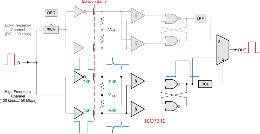
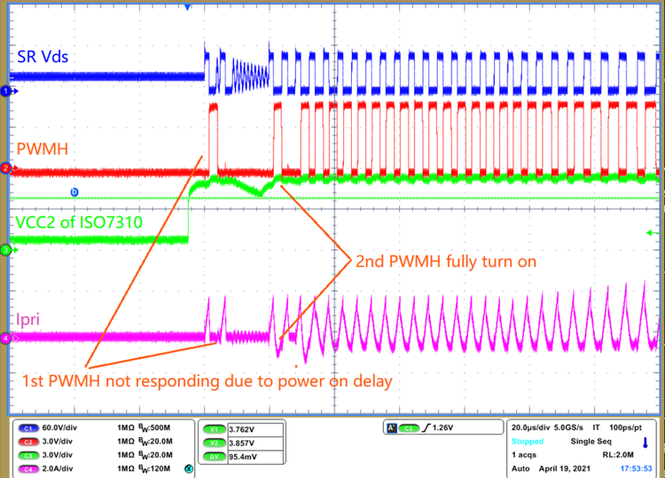
Change isolator driver from level-based driver to edge-based driver Figure 4-13, such as ISO7310, it can prevent partial response to PWMH. Then SR is able to ZCS turn off to avoiding over stress. After change to ISO7310, The waveforms shown in Figure 4-14.
 Figure 4-12 Level Based Isolation Driver
Architecture
 Figure 4-13 Edge Based Isolation Driver
Architecture
 Figure 4-14 Isolator Change to
ISO7310