SLUAAJ7 June 2022 UCC256402 , UCC256403 , UCC256404
- Abstract
- Trademarks
- 1UCC25640x Selection Guide
- 2UCC25640x Features Brief Overview
- 3UCC25640x Power Up Guidelines and Debugging Notes
- 4References
2.2.2 Detecting AC presence
- HV pin is connected to Line and Neutral through two rectifier diodes as shown in Figure 2-4; This pin’s voltage is used to detect if AC is present.
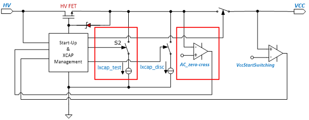
- Under ideal conditions when AC is connected, the HV pin should detect the zero crossing where the voltage between Line and Neutral reaches 0 V twice per cycle. However, due to the parasitic capacitance of the diode bridge, the voltage at HV will not reach zero. To overcome this, current is sinked from HV to GND.
 Figure 2-6 X-cap discharge internal block
diagram
Figure 2-6 X-cap discharge internal block
diagram- The switch S2 highlighted in Figure 2-6 controls the Ixcap test current to determine if AC is still connected. The logic is looking for the HV pin to be pulled below 9V. Note this test current goes to gnd.