SLUAAL3 July 2022 UCC28C50-Q1 , UCC28C51-Q1 , UCC28C52-Q1 , UCC28C53-Q1 , UCC28C54-Q1 , UCC28C55-Q1 , UCC28C56H-Q1 , UCC28C56L-Q1 , UCC28C57H-Q1 , UCC28C57L-Q1 , UCC28C59-Q1
1 Introduction
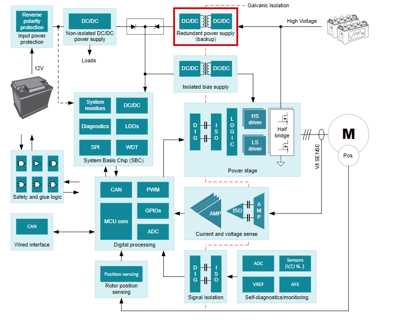
The traction inverter efficiently converts DC power from a high-voltage battery to alternating phases of power needed to drive multi-phase motors. Galvanic isolation is required to protect people, as well as the low-voltage components on the cold side of the system, from the high-voltage traction inverter on the hot side of the system. As automotive applications continue to trend in the direction of increased safety, it has become more common to include a high-voltage to low-voltage backup supply in the traction inverter system. The backup power supply powers the low-voltage components if the 12-V battery fails. Figure 1-1 displays an example block diagram featuring the high-voltage to low-voltage redundant power supply.
Also, Silicon Carbide (SiC) MOSFETs are becoming more and more prevalent in the industry too. For an 800VTYP EV/HEV battery system, the primary-side switching device of the isolated bias supply once required two silicon MOSFETs in a cascode configuration. The cascode configuration is employed in TI’s PMP41009 reference design. Those two MOSFETs can now be replaced by a single 1700V SiC MOSFET saving component cost, condensing PCB area, and reducing losses to produce higher efficiency.
To operate efficiently with their lowest RDS,ON, SiC MOSFETs require higher gate drive voltages than silicon MOSFETs. To drive SiC MOSFETs reliably and efficiently, Texas Instruments has introduced the new auto-grade UCC28C5x current-mode PWM controllers with higher ABS MAX voltage of the VDD pin (30V) and additional/increased options for the UVLO Start/Stop thresholds, VDDON and VDDOFF in the data sheet. With 30 V VDD rating, the gate drive voltage at the OUT pin can easily be adjusted to support a variety of SiC MOSFETs with different optimal gate voltage levels, such as 20 V, 18 V, or 15 V. A proper VDDOFF level is also a very critical consideration to avoid the risk of thermal runaway issue of SiC MOSFETs. Compared to the UCC28C4x family, other improvements include reduced startup and operating currents, and improved accuracy of the reference voltage.
Table 1-1 and Table 1-2 are summaries of the new UCC28C5x-Q1 controllers dedicated to SiC MOSFET applications and their enhancements over the preceeding UCC28C4x-Q1 family.
| UVLO | Maximum Duty Cycle | Temperature (TJ) | ||
|---|---|---|---|---|
| Turn On at 18.8
V Turn Off at 15.5 V Suitable for 20-VGS SiC MOSFETs |
Turn On at 18.8
V Turn Off at 14.5V Suitable for 18-VGS SiC MOSFETs |
Turn On at 16 V
Turn Off at 12.5V Suitable for 15-VGS SiC MOSFETs |
||
| UCC28C56H-Q1 | UCC28C56L-Q1 | UCC28C58-Q1 | 100% | –40°C to 150°C |
| UCC28C57H-Q1 | UCC28C57L-Q1 | UCC28C59-Q1 | 50% | |
| Parameter | UCC28C4x-Q1 | UCC28C5x-Q1 |
|---|---|---|
| Supply current at 52 kHz | 2.3 mA | 1.3 mA |
| Start-up current | 100 µA | 75 µA |
| VDD absolute maximum | 20 V | 30 V |
| Reference voltage accuracy | ± 2% | ± 1% |
| UVLO and DMAX for Si MOSFET | 6 options | 6 options |
| UVLO and DMAX for SiC MOSFET | no options | 6 options |
 Figure 1-1 Traction Inverter Block Diagram
The high-voltage to low-voltage backup supply presents new challenges compared to the low-input voltage flyback converters tapped from the 12-V battery that currently dominate HEV and EV powertrains. The high-voltage input flyback converter needs to support ultra-wide input voltages. The backup supply needs to operate down to 40 V to support functional safety tests during regenerative braking of the traction motor. This enables engineers and mechanics to work safely. The second safety critical scenario is when the car is towed or pushed (maybe during an accident). In this case the motor becomes a generator and charges up the high voltage input bus capacitor of the traction inverter. In both cases, the backup supply needs to start operation relatively fast to provide the bias power to the isolated gate driver such that the drivers can short the motor windings and prevent the bus capacitor from charging above 60 V. These considerations require the total startup time of the backup supply to be hundreds of milli-seconds, across the range of input voltages.
A 1000 V maximum input-voltage is usually required in 800-V battery systems, considering the battery charged voltage, the AC ripple through the harness, and design margin. Additional challenges, which arise from operating off the high-voltage battery, are selecting a high-voltage power device, minimizing start-up losses, minimizing noise coupling, and ensuring the system meets safety standards.
The flyback topology is the most popular redundant power supply solution due to a low cost, and the ability to support a wide input-voltage range. A controller from the recently expanded and improved UCC28C5x-Q1 family is well suited for this application. When designing a redundant, flyback power supply, all of these design requirements must be addressed.