SLUP408 February 2022 LM25149-Q1 , LM61460-Q1 , LM61495-Q1 , LMQ61460-Q1
- 1 Introduction
- 2 Defining EMI
- 3 What Causes EMI in a Switched-Mode DC/DC Regulator?
- 4 Existing Passive EMI Filtering Techniques
- 5 Passive Filter Limitations
- 6 AEF
- 7 Spread Spectrum
- 8 DRSS
- 9 True Slew-Rate Control
- 10HotRod™ Package Technology
- 11Optimized Package and Pinout
- 12Integrated Capacitors
- 13Conclusions
- 14References
- 15Important Notice
9 True Slew-Rate Control
Slew-rate control is the ability to slow down the rising switch-node voltage and current in a buck regulator to reduce high-frequency emissions. At a high-enough frequency, the switch-node square wave will begin to look like a trapezoid wave with harmonics rolling off at 40 dB/dec, as shown in Figure 9-1. The ability to slow down the slew rate by controlling the drive strength of the high-side field-effect transistor’s (FET) driver enables the harmonics to roll off at lower frequencies, thereby reducing the overall noise amplitude measurement and providing more margin below violation limits in industry EMI standards.
 Figure 9-1 EMI emission of a square
wave.
Figure 9-1 EMI emission of a square
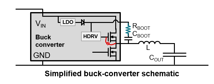
wave.One conventional way to control the slew rate in a buck regulator is to place a resistor in series with the boot capacitor, as shown in Figure 9-2. An unintended consequence of adding RBOOT is that the bootstrap voltage of the high-side driver may drop below its undervoltage lockout as peak gate-drive currents flow through it, affecting normal operation of the buck converter.
 Figure 9-2 Conventional slew-rate control
method.
Figure 9-2 Conventional slew-rate control
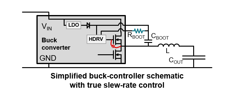
method.Implemented in buck converters such as the LM61460-Q1 and LM61495-Q1, an improved slew-rate control method uses a dedicated pin (RBOOT). Figure 9-3 shows a true slew-rate control feature with a dedicated boot resistor that controls the drive strength of the high-side FET’s driver. A higher RBOOT resistance yields slower switch-node rise times. Accurately controlling the rise time of the switch-node voltage makes it possible to precisely control the switch-node harmonics’ rolloff frequency, which effectively improves the noise amplitude measurement. In some applications, true slew-rate control can eliminate the need for shielding and common-mode chokes, which further reduces total solution size.
 Figure 9-3 The true slew-rate control
method.
Figure 9-3 The true slew-rate control
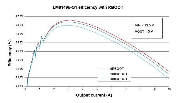
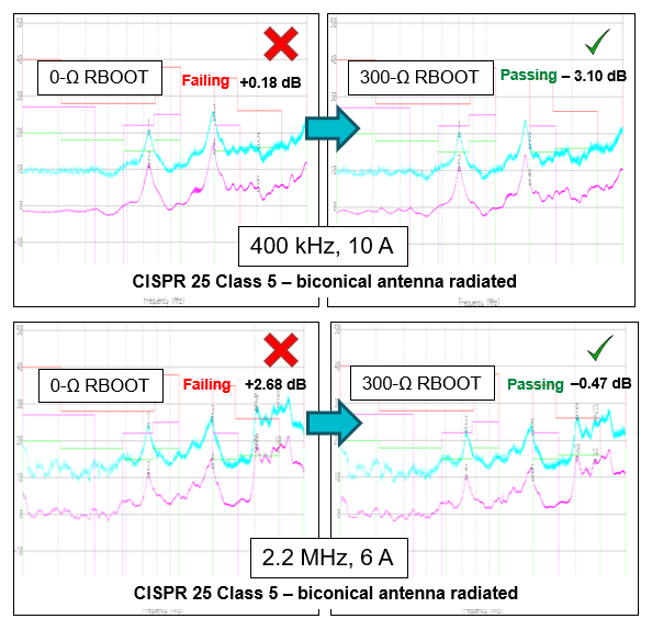
method.As tested, increasing the RBOOT value from 0 Ω to 300 Ω results in an approximate 0.5% drop in efficiency (as shown in Figure 9-4) but yields a solution that is CISPR 25 Class 5-compliant (as shown in Figure 9-5).
 Figure 9-4 Efficiency comparisons with
different RBOOT resistors.
 Figure 9-5 CISPR 25 EMI comparisons with
different RBOOT resistors.