SLUP409B April 2022 – April 2024 TPS543320 , TPS543620 , TPS543820 , TPS62913 , TPS62916
- 1
- Abstract
- 1 Introduction
- 2 DC/DC Converters are Noisy
- 3 Power-Supply Output Voltage Ripple and Noise Degrade ADC Performance
- 4 Minimizing Low-Frequency Noise Requires Dedicated Low-Noise IC Technologies
- 5 Traditional Approaches to Reducing Ripple
- 6 Using Smaller Capacitors in Parallel
- 7 Larger Inductance
- 8 Adding a Feedthrough Capacitor
- 9 Adding a Ferrite Bead
- 10Layout Techniques
- 11Silicon Solutions
- 12Conclusions
5 Traditional Approaches to Reducing Ripple
Traditional approaches to reducing output ripple include adjusting the standard inductor-capacitor (LC) output filter and adding more filtering after it. To compare approaches, take measurements using TI’s TPS543620 buck converter evaluation module (EVM). Figure 5 shows the simplified schematic for the EVM.
 Figure 5 TPS543620 EVM simplified
schematic.
Figure 5 TPS543620 EVM simplified
schematic.The low output voltage ripple target of 200µVpp that we described earlier necessitates a low-noise test setup to accurately measure the ripple. A 1-to-1 probe using a coaxial cable provides the best resolution in the measurement. Avoid using a 10-to-1 probe with high-impedance termination at the oscilloscope for low-ripple measurements, as the probe can limit the minimum voltage scale of the oscilloscope and add noise to the measurement, pushing the noise floor near the amplitude of the ripple you are trying to measure. Use SMA or SMB connectors to connect the coax cable to the measurement point.
Taking the measurement with full bandwidth requires proper termination to prevent noise pickup and block reflections on the coax cable.
There are two ways to terminate the measurement:
- Use a DC blocker to enable oscilloscope use with a 50-Ω termination and DC coupling. For many scopes, AC coupling is not possible with a 50-Ω termination.
- Add a series 50-Ω resistor between the coax cable and the point at which you are measuring the output voltage. This configuration makes it possible to configure the scope for high-impedance termination and AC coupling.
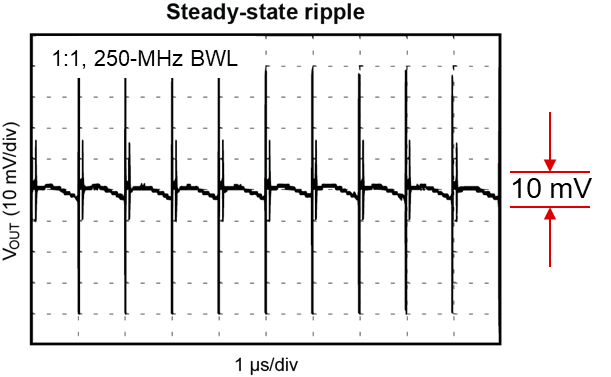
The steady-state ripple is taken at full 6-A load, with a high bandwidth limit (BWL) of 250MHz to include the high-frequency switching noise in the measurement. A typical target for an application not requiring low output ripple is 1% peak-to-peak, or 10mV for a 1-V output. Measuring the fast Fourier transform (FFT) of the output voltage at a full 6-A load but with a 1-GHz BWL offers even better insight into the frequency components of the output ripple. In the time domain, the ripple is the addition of all of the different frequency components, making it very difficult to determine the contribution from any particular frequency.
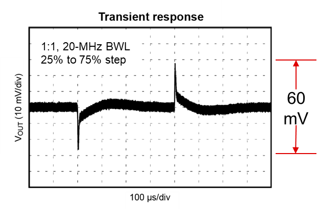
Taking the transient response measurement with a 20-MHz BWL removes high-frequency switching noise and serves two purposes. First, you can use the transient response to judge the control stability, as some filtering techniques can reduce the gain and phase margin. Second, you can monitor the transient response to see if it is worse after adding filtering. Some applications, such as digital power rails for high-speed AFEs in wireless infrastructure applications, require power supplies with low ripple and a fast transient response. A typical target is ±3%, or 60-mV peak-to-peak for a 1-V output with a 25% to 75% step, or 1.5A to 4.5A for a 6-A maximum load.
Figure 6, Figure 7 and Figure 8 show the results of these three measurements on the unmodified TPS543620 EVM. As Figure 6 illustrates, the 250-MHz BWL exceeds the 10-mV target because of the high-frequency switching noise above 100MHz, as shown in the FFT of Figure 8. Output ripple measurements and requirements necessitate only a 20-MHz BWL, which would result in a measured ripple below the 10-mV requirement.
 Figure 6 Unmodified TPS543620 EVM
output ripple.
 Figure 7 Unmodified TPS543620 EVM
transient response.
 Figure 8 Unmodified TPS543620 EVM
output FFT.