SLUUCC3 february 2021 BQ79631-Q1
- 1
- Abstract
- Trademarks
- General Texas Instruments High Voltage Evaluation (TI HV EVM) User Safety Guidelines
- 1General Description
- 2Theory of Operation
- 3Connectors
- 4Quick Start Guide
- 5Physical Dimensions
- 6BQ79631-Q1 EVM Schematic, Assembly, Layout, and BOM
3.3.4 Switches
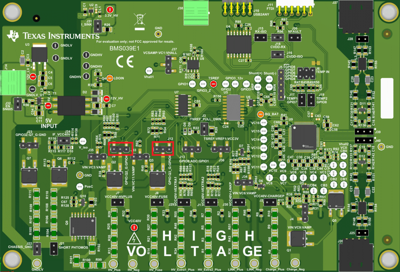
In each of the high voltage networks on the BQ79631EVM, there are MOSFET switches controlled by GPIO pins that can disconnect the high voltage inputs from the rest of the network. These switches must always remain on while a measurement is taking place but can be turned off to block any leakage current from escaping the battery pack while not in use. These switches are controlled by the GPIO2 pin by default, but switches connected to the HV_Plus and HV_Fuse network can be controlled by GPIO4 by moving the shunt from pins 1-2 over to pins 2-3 on jumpers J9 and J12, respectively.
 Figure 3-4 GPIO4 Control Option
To close the switch and enable current to flow through each network, the user must set the associated GPIO pin to output high from within the GUI.
If the user wishes to use the EVM to test without use of the included switches, then simply populate the following resistor slots with a 0-Ω resistor.
| Resistor # on EVM | Switch Being Bypassed | Network |
|---|---|---|
| R39 | Q2 | HV_Plus |
| R40 | Q3 | HV_Fuse |
| R17 | Q1 | Charge_Plus |
| R73 | Q5 | Charge_Neg |
| R113 | Q6 | Insulation Detection |