SLUUCC3 february   2021 BQ79631-Q1


  1.   1
  2.   Abstract
  3.   Trademarks
  4.   General Texas Instruments High Voltage Evaluation (TI HV EVM) User Safety Guidelines
  5. 1General Description
    1. 1.1 Key Features
      1. 1.1.1 Key Electrical Parameters
  6. 2Theory of Operation
    1. 2.1 Single Board
    2. 2.2 Stacked Systems
  7. 3Connectors
    1. 3.1 Powering the BQ79631EVM
    2. 3.2 Primary Input and Output Connectors
      1. 3.2.1 Jumper Placements
      2. 3.2.2 Host Interface
      3. 3.2.3 High-Side and Low-Side Communications
    3. 3.3 High Voltage Networks
      1. 3.3.1 High Voltage Safety Considerations
      2. 3.3.2 High Voltage Connections
      3. 3.3.3 High Voltage Alternatives
      4. 3.3.4 Switches
      5. 3.3.5 Buffers
      6. 3.3.6 Insulation Detection Network
    4. 3.4 Current Sense
      1. 3.4.1 SRP/SRN
      2. 3.4.2 VCSamp_Out
    5. 3.5 GPIO Connections
  8. 4Quick Start Guide
    1. 4.1 Launch Pad Connection and Example Code
      1. 4.1.1 Required Devices for Using the Example Code
      2. 4.1.2 Power Connections
      3. 4.1.3 Connecting the EVM to the TMS570 LaunchPad
      4. 4.1.4 Software
    2. 4.2 USB2ANY Connection with GUI
      1. 4.2.1 GUI
      2. 4.2.2 GUI UART Connection
  9. 5Physical Dimensions
    1. 5.1 Board Dimensions
  10. 6BQ79631-Q1 EVM Schematic, Assembly, Layout, and BOM
    1. 6.1 Schematics
    2. 6.2 Layout
    3. 6.3 Bill of Materials

High Voltage Safety Considerations

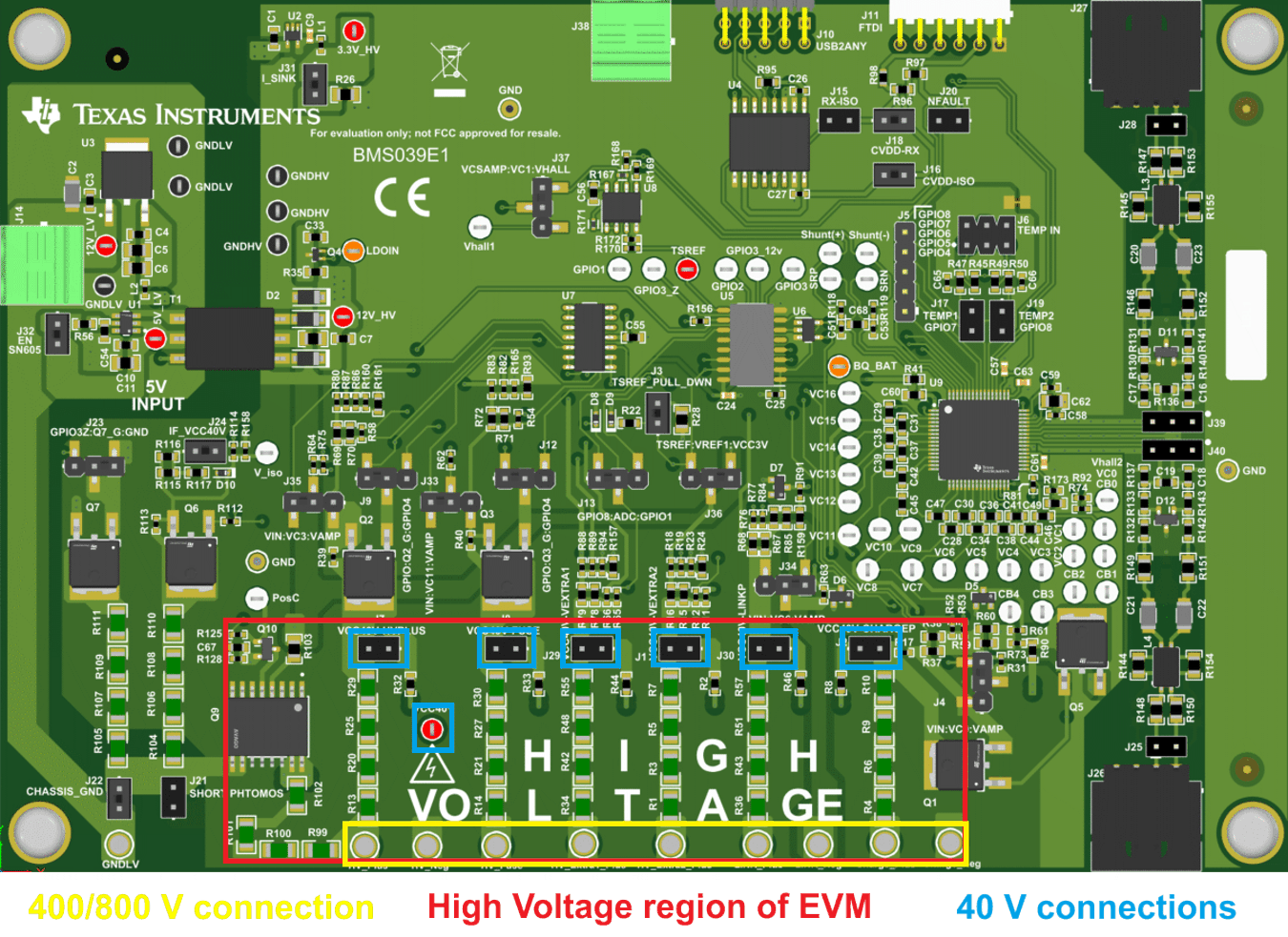
When connecting to any of the high voltage networks, TI recommends that extreme safety precautions are taken. The user must assume the entire board is live with high voltage once an HV connection is made. The high voltage connection points and the areas on the EVM where these voltages are dissipated are shown in the figure below. Extra care must be taken around this area of the EVM.
GUID-20200717-CA0I-4C1T-5JVK-80FB95ZWQQKF-low.png Figure 3-3 High Voltage Connections