SLUUCC4A October 2020 – September 2021 TPS92520-Q1
- Trademarks
- General Texas Instruments High Voltage Evaluation (TI HV EMV) User Safety Guidelines
- 1Description
- 2Performance Specifications
- 3Performance Data and Typical Characteristic Curves
- 4Schematic, PCB Layout, and Bill of Materials
- 5Software
- 6TPS92520EVM-133 Power Up and Operation
- 7Revision History
5.4 Checking for Updates
This section shows the detailed instructions for checking if there is an update and how to install it. Run the TPS92518, 520, 682 LaunchPad Evaluation Software and go to the Help menu, see Figure 5-20.
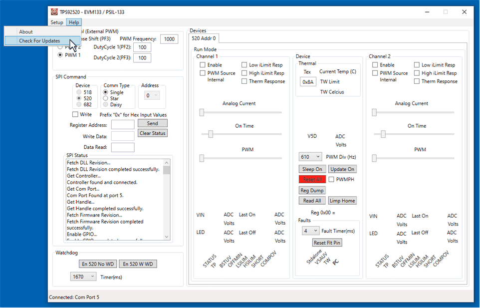 Figure 5-20 Help Menu and Checking for Updates
Click Check for Updates > to run updater.
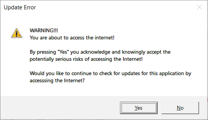 Figure 5-21 Update Screen 1
Click Yes > to accept risks for accessing the Internet.
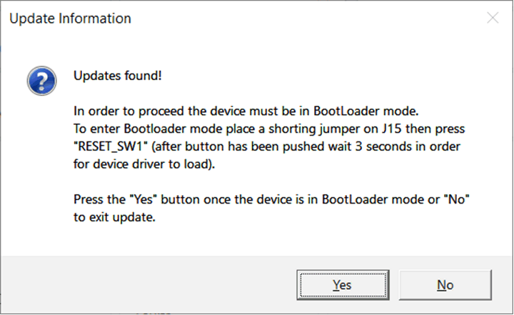 Figure 5-22 Update Screen 2
Go to the LEDMCUEVM-132 (PSIL-132) and locate J15 and RESET_SW1. Install shorting jumper at J15 locations as seen and then press the RESET_SW1 as seen in Figure 5-23. This action places the MCU in Bootloader mode.
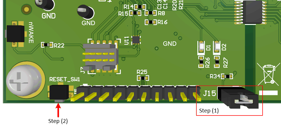 Figure 5-23 J15 Jumper and RESET_SW1 Switch for Bootloader Mode
Click Yes > to run the updater. The LPP Updater will run and once finished will ask if you would like to re-launch the GUI applications.
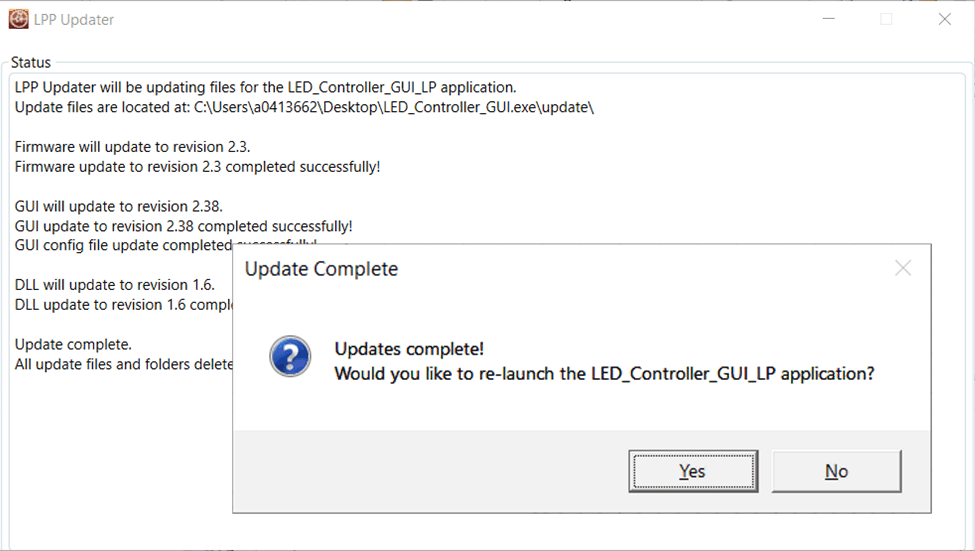 Figure 5-24 Setup Screen 5
Click Yes > to re-launch GUI.
A window appears indicating the the LEDMCUEVM-132 must be changed from bootloader mode to normal mode. This is accomplished by removing the shorting jumper from J15 then pressing the "RESET_SW1" switch and wait 3 seconds to ensure device drivers reload, see Figure 5-26.
 Figure 5-25 Setup Screen 6
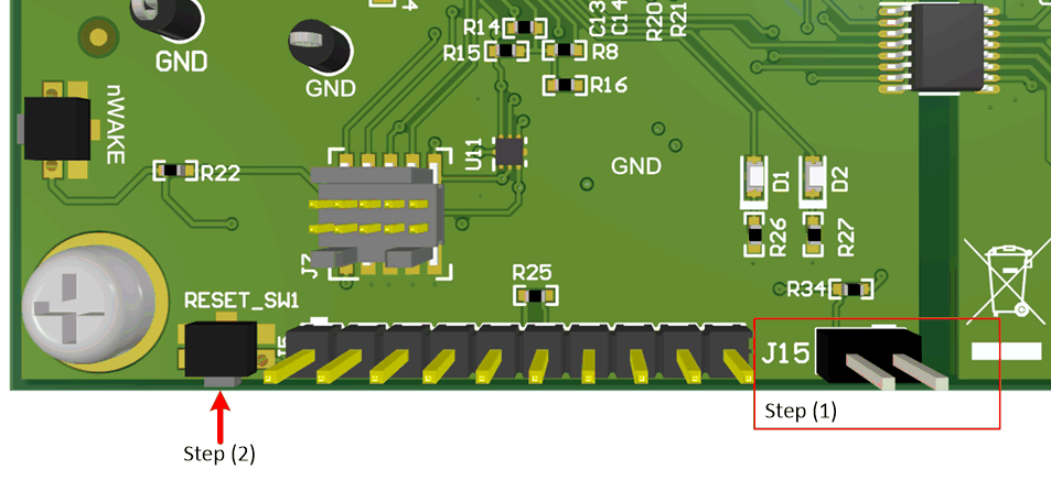 Figure 5-26 15 Jumper and RESET_SW1 Switch for Normal Mode
Click the OK > button to restart the GUI.