SLUUCC4A October 2020 – September 2021 TPS92520-Q1
- Trademarks
- General Texas Instruments High Voltage Evaluation (TI HV EMV) User Safety Guidelines
- 1Description
- 2Performance Specifications
- 3Performance Data and Typical Characteristic Curves
- 4Schematic, PCB Layout, and Bill of Materials
- 5Software
- 6TPS92520EVM-133 Power Up and Operation
- 7Revision History
6.5 GUI Devices Window
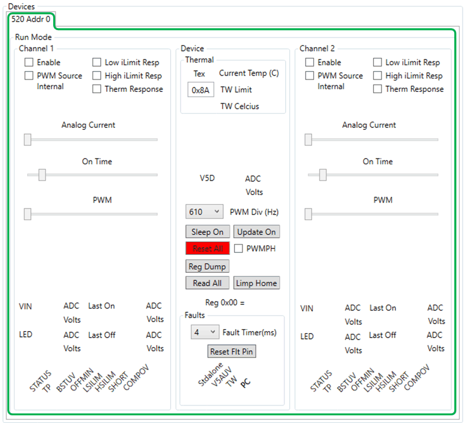
The device command window will not do any reads of the device until the En 520 No WD button has been selected and the watch dog timer has been disabled, see Figure 6-18 .
 Figure 6-18 Device Command Window
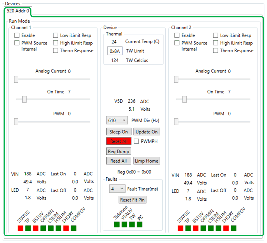
Once the En 520 No WD has been selected, the GUI will perform an initial read of all the registers and load the information into the device command window, shown in Figure 6-19. Note that SHORT, BSTUV, and STATUS are flagged red because those faults conditions have occurred. The SHORT fault condition occurs because the output is off and no current is driving the LEDs and the voltage at the output is less than 2.45 V on the CSP pin, which indicates a SHORT condition. BSTUV fault indicates that the bootstrap supply is lower than 2.95 V, which is correct because the booststrap voltage is created when the output is turned on and the switch node is pulled to ground to charge the booststrap capacitor to drive the high-side FET. STATUS fault indicates that a fault has occurred and is the logic OR of the fault bits for that channel.
The GUI is split up into different sub windows for each the Devices. There can be multiple tabs (Devices) and each tab will be for a specific device at at specific SPI address. Figure 6-19 shows the TPS92520 (520) as the device and the address (Addr) is 0.
 Figure 6-19 Devices Window After
Watchdog is Disabled.