SLUUCE3 June 2021 UCC27614
5.1 Power Up
- Before beginning the power up test procedure, verify the connections with Figure 4-1.
Connect INB_IN test point to GND test point with jumper if the UCC27614EVM is being evaluated in non-inverting configuration.
- Enable supply #1, if the current on DMM1 is more than 0.25 mA and less than 0.71 mA, everything is set correctly.
- The following conditions should be present:
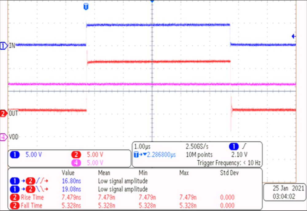
- Stable pulse output on channel-1 and channel-2 of the oscilloscope, refer to Figure 5-1
Stable pulse output on the Ch-A of the oscilloscope, as per Figure 2.
- Frequency measurement should be 100 kHz, ±5 kHz or equal to the programmed function generator frequency
- DMM #1 should display around 4.6 mA, ±2 mA with the default load capacitance of 1.0 nF. For more information about operating current, see the UCC27614 Single Channel 30V 10A High Speed Low Side Gate Driver Data Sheet.
 Figure 5-1 Example Input and Output Waveforms (Green and Magenta are PWM Inputs, Yellow and Blue are Driver Outputs)