SLUUCE3 June 2021 UCC27614
4.3.6 Bench Setup Diagram
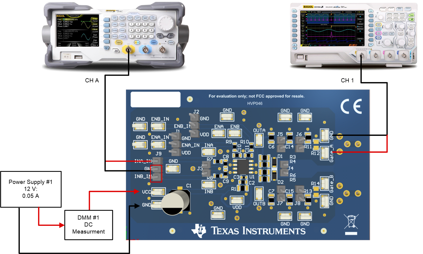
The bench setup diagram includes the function generator and oscilloscope connections.
Use the following connection procedure, refer to Figure 4-1.
For the UCC27614EVM, connection procedure is as follow:
- First, make sure the output of the function generator and power supplies are disabled before connection.
- Apply function generator channel-A on INA_IN+ to GND.
Function generator Ch-A channel applied on INA_IN, see in Figure 6.2;
Power supply #1: positive node connected to input of DMM #1 and DMM #1 output connected to test point marked as VCC, negative node of Power Supply #1 connected directly to test point marked as GND; see in Figure 6.2;
Connect oscilloscope Ch-1 probes to test points marked as Gate_A ßà GND, smaller measurement loop is preferred; see in Figure 6.2;
 Figure 4-1 Bench Setup Diagram and Configuration