SLUUCG4 November 2022 TPS548C26
1.1 Description
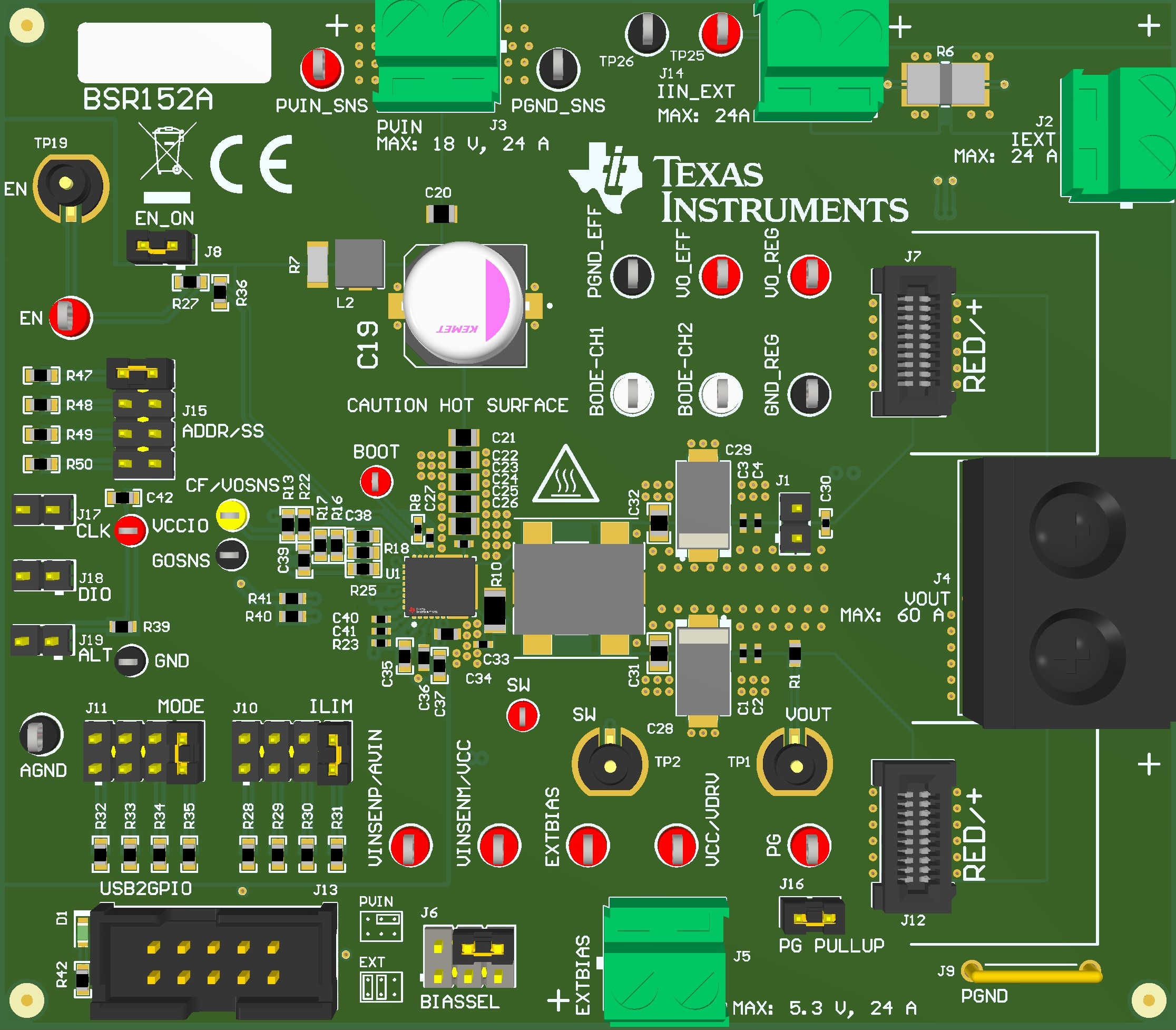
The TPS548C26EVM is an evaluation module for the TPS548C26 DC/DC synchronous buck converter. The evaluation module accepts an 8-V to 16-V input and can deliver an output current up to 35 A. The converter uses D-CAP+™ control scheme for fast transient response, using less output capacitance to save board space. Rated input voltage and output current range for the evaluation module are given in Table 1-1. Figure 1-1 highlights the user interface items associated with the EVM.
The high-side and low-side MOSFETs are incorporated inside the package along with the gate-drive circuitry. The low drain-to-source on-resistance of the MOSFET allows the to achieve high efficiencies and helps keep the junction temperature low at the rated output current. Fixed frequency advanced current mode control allows you to synchronize the regulators to an external clock source. An external divider allows for an adjustable output voltage. The FSEL and MODE pins provide selectable switching frequency, soft-start time, current limit, and internal compensation. Lastly, the TPS548C26 includes an enable pin and a power-good output which can be used for sequencing multiple regulators.
| EVM | INPUT VOLTAGE RANGE | OUTPUT CURRENT RANGE |
|---|---|---|
| TPS548C26EVM | 8 V to 16 V | 0 A to 35 A |
 Figure 1-1 EVM User Interface