SLUUCT6 April 2024 BQ25186
4.1 Schematics
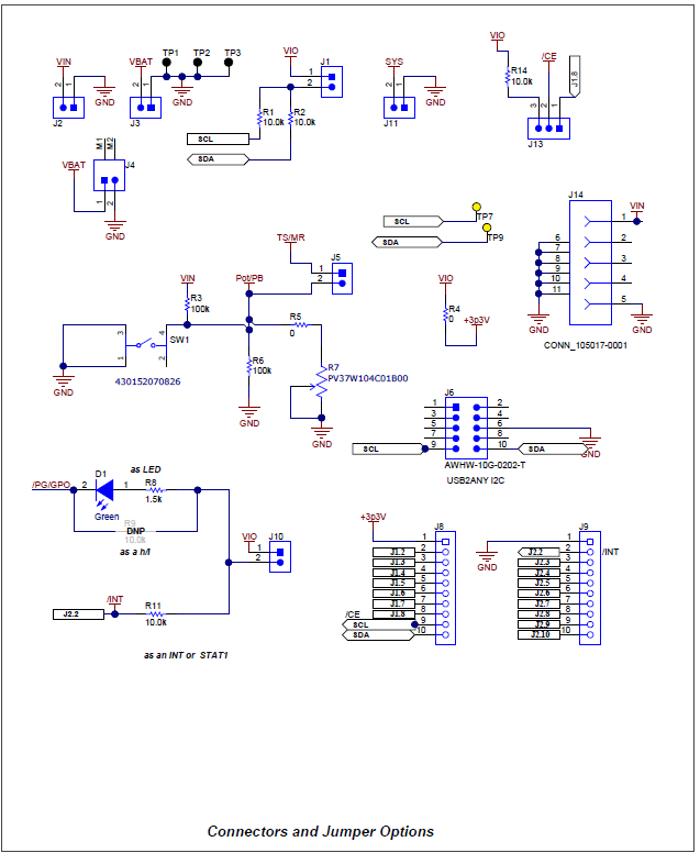
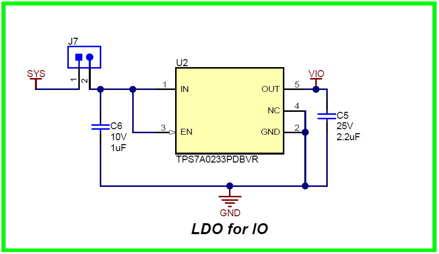
Figure 5-1 through Figure 5-3 illustrate the EVM schematics.
 Figure 4-1 BQ25186EVM Schematic
 Figure 4-2 BQ25186EVM Jumper Connectors
 Figure 4-3 LDO for Other Peripherals
SLUUCT6 April 2024 BQ25186
Figure 5-1 through Figure 5-3 illustrate the EVM schematics.
 Figure 4-1 BQ25186EVM Schematic
 Figure 4-2 BQ25186EVM Jumper Connectors
 Figure 4-3 LDO for Other Peripherals