SLVAEE5 June 2020 TPS23754
2 Detailed Description Using the TPS23754
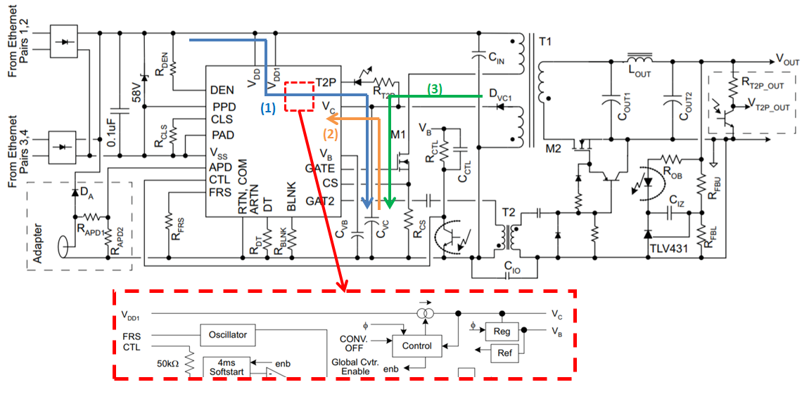
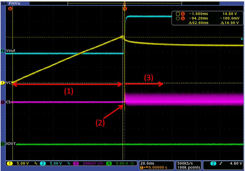
Figure 3 shows that when the standard PoE voltage range feeds VDD bus after PoE handshaking or adapter plug-in, the internal constant current source will be triggered to start charging the external Cvc capacitor. The voltage on Cvc is a constant rising slope until reaching to 15V,typ. The charging current path to external Cvc is (1). Therefore, the controller starts sending PWM pulse to switch the external primary FET M1 while the internal current source of controller is turned off. Before the output voltage (Vout) achieves the target Vout, the external Cvc capacitor is providing the energy as discharging to Vc pin as the source of the internal gate driver. The current path is (2). After Vout achieves the target voltage, the AUX winding start providing the energy to the internal gate driver and recharging Cvc capacitor. The current path is (3) and the waveform is shown in Figure 4.
 Figure 3. Cvc Current Path During the Startup
  Figure 4. Startup waveform on Cvc