SLVAEF4C august 2019 – may 2023 TPS7H4001-SP
PRODUCTION DATA
- 1
- Single-Event Effects Test Report of the TPS7H4001-SP
- Trademarks
- 1 Introduction
- 2 Single-Events Effects (SEE)
- 3 Test Device and Evaluation Board Information
- 4 Irradiation Facility and Setup
- 5 Depth, Range, and LETEFF Calculation
- 6 Test Setup and Procedures
- 7 Destructive Single-Event Effects (DSEE)
- 8 Single-Event Transients (SET)
- 9 Summary
- 10Total Ionizing Dose (TID) From SEE Experiments
- 11References
- 12Revision History
7.2 Single Event Latch-Up (SEL) Results
SEL characterization was performed with forced hot air to maintain the die temperature at 125°C during the tests. A K-type thermocouple attached to the thermal pad vias (on the bottom side of the EVM) with thermal paste was used to monitored the temperature. The thermocouple was hold on place by using high temperature tape (kapton-tape). The thermocouple and die temperature were verified using a thermal IR camera, prior to the SEE test campaign.
The device was exposed to Silver (109Ag), Praseodymium (141Pr), and Holmium (165Ho) ions. For 109Ag angles of incidence of 0° and 25° were used for an LETEFF of 49.3 and 54.8 MeV·cm2/mg, respectively. 141Pr at angles of incidence of 0° and 27.3° were used for an LETEFF of 66.37 and 74.95 MeV·cm2/mg, respectively. 165Ho at angle of incidence of 0° was used for an LETEFF of 75.82 MeV·cm2/mg. For Silver and Praseodymium the air distance between the heavy-ion exit port and the DUT was set to 40-mm for all runs. In the case of Holmium the distance was set to 30-mm. Flux of ≈105 ions/cm2·s and fluence of ≥ 107 ions/cm2 per run were used for the SEL characterization. Run duration to achieve this fluence was approximately 2 minutes.
The SEL test condition and results are summarized in Table 7-3. The TPS7H4001-SP is DSEE-free when operated withing the green area under the SOA curve, presented in Figure 7-1. For more details on the DSEE cross section refer to Section 7.1.
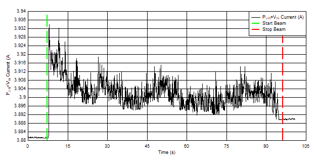
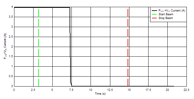
Current vs time plot for run #3 (no damage) and run # 6 (damage) is shown in Figure 7-2 and Figure 7-3, respectively.
During the high-temperature characterization of the TPS7H4001-SP, the output voltage was monitored for transients –3% ≤ VOUT ≤ 3% from the nominal voltage of ≈1 V (±30 mV), using the DPO7104C. Transients were observed at these conditions and in general the device behaved as described in Section 8, however a few upsets occurred where the output voltage dropped near zero with a long recovery time (≈2 ms). During this type of upset, the SS voltage dropped and initiate a restart cycle of the device. When this occurs, the recovery time is governed by the CSS capacitor. For the case of the configuration used during the testing campaign of the TPS7H4001-SP the CSS was set to 39 nF (≈2 ms).
| Run # | Unit # | Ion Type | Angle of Incidence (°) | LETEFF (MeV·cm2 /mg) | Flux (ions/cm2·s) | Fluence (ions/cm2) | PVIN = VIN (V) | Load (A) | Damage? |
|---|---|---|---|---|---|---|---|---|---|
|
1 |
1 |
165Ho |
0 |
75.82 |
1.06E+05 |
1.00E+07 |
7 |
18 |
No |
|
2 |
1 |
165Ho |
0 |
75.82 |
1.01E+05 |
1.00E+07 |
7 |
18 |
No |
|
3 |
2 |
165Ho |
0 |
75.82 |
1.15E+05 |
1.00E+07 |
7 |
18 |
No |
|
4 |
3 |
165Ho |
0 |
75.82 |
1.18E+05 |
2.61E+06 |
7 |
18 |
Yes |
|
5 |
4 |
165Ho |
0 |
75.82 |
8.59E+04 |
9.99E+06 |
7 |
18 |
No |
|
6 |
5 |
141Pr |
27.3 |
74.95 |
1.01E+05 |
4.15E+05 |
7 |
18 |
Yes |
|
7 |
6 |
141Pr |
0 |
66.37 |
1.08E+05 |
5.25E+06 |
7 |
18 |
Yes |
|
8 |
7 |
141Pr |
0 |
66.37 |
1.07E+05 |
9.96E+06 |
6.5 |
18 |
No |
|
9 |
7 |
141Pr |
0 |
66.37 |
1.09E+05 |
1.00E+07 |
6.75 |
18 |
No |
|
10 |
7 |
141Pr |
0 |
66.37 |
1.04E+05 |
1.00E+07 |
7 |
18 |
No |
|
11 |
8 |
141Pr |
27.3 |
74.95 |
1.12E+05 |
4.34E+06 |
6.5 |
18 |
Yes |
|
12 |
9 |
141Pr |
27.3 |
74.95 |
1.10E+05 |
9.96E+06 |
6 |
18 |
No |
|
13 |
9 |
141Pr |
27.3 |
74.95 |
1.09E+05 |
1.00E+07 |
6.25 |
18 |
No |
|
14 |
9 |
141Pr |
27.3 |
74.95 |
9.71E+04 |
1.00E+07 |
6.5 |
18 |
No |
|
15 |
9 |
141Pr |
27.3 |
74.95 |
9.40E+04 |
1.00E+07 |
6.75 |
18 |
No |
|
16 |
9 |
141Pr |
27.3 |
74.95 |
9.07E+04 |
9.99E+06 |
7 |
18 |
No |
|
17 |
9 |
141Pr |
27.3 |
74.95 |
1.06E+05 |
1.00E+07 |
6.5 |
18 |
No |
|
18 |
9 |
141Pr |
27.3 |
74.95 |
1.05E+05 |
9.99E+06 |
6.75 |
18 |
No |
|
19 |
9 |
141Pr |
27.3 |
74.95 |
1.11E+05 |
1.00E+07 |
7 |
18 |
No |
|
20 |
10 |
141Pr |
27.3 |
74.95 |
1.03E+05 |
6.91E+06 |
7 |
18 |
Yes |
|
21 |
11 |
141Pr |
27.3 |
74.95 |
9.75E+04 |
1.00E+07 |
6 |
18 |
No |
|
22 |
11 |
141Pr |
27.3 |
74.95 |
1.01E+05 |
2.70E+06 |
6.5 |
18 |
Yes |
|
23 |
12 |
141Pr |
27.3 |
74.95 |
1.04E+05 |
1.00E+07 |
6.25 |
18 |
No |
|
24 |
12 |
141Pr |
27.3 |
74.95 |
9.84E+04 |
9.96E+06 |
6.375 |
18 |
No |
|
25 |
12 |
141Pr |
27.3 |
74.95 |
9.58E+04 |
2.40E+06 |
6.5 |
18 |
Yes |
|
26 |
13 |
141Pr |
0 |
66.37 |
1.08E+05 |
1.71E+06 |
6.5 |
18 |
Yes |
|
27 |
14 |
141Pr |
0 |
66.37 |
1.06E+05 |
1.00E+07 |
6.25 |
18 |
No |
|
28 |
14 |
141Pr |
0 |
66.37 |
1.10E+05 |
1.00E+07 |
6.4 |
18 |
No |
|
29 |
14 |
141Pr |
0 |
66.37 |
1.08E+05 |
1.00E+07 |
6.5 |
18 |
No |
|
30 |
14 |
141Pr |
0 |
66.37 |
1.13E+05 |
9.95E+06 |
6.6 |
18 |
No |
|
31 |
14 |
141Pr |
0 |
66.37 |
1.11E+05 |
1.00E+07 |
6.8 |
18 |
No |
|
32 |
14 |
141Pr |
0 |
66.37 |
1.13E+05 |
9.99E+06 |
7 |
18 |
No |
|
33 |
15 |
141Pr |
27.3 |
74.95 |
1.15E+05 |
9.98E+06 |
7 |
9 |
No |
|
34 |
15 |
141Pr |
27.3 |
74.95 |
1.22E+05 |
7.81E+06 |
7 |
13.5 |
Yes |
|
35 |
16 |
141Pr |
27.3 |
74.95 |
1.13E+05 |
2.24E+06 |
7 |
11 |
Yes |
|
36 |
17 |
141Pr |
27.3 |
74.95 |
1.06E+05 |
9.08E+06 |
7 |
10 |
No |
|
37 |
17 |
141Pr |
27.3 |
74.95 |
9.97E+04 |
9.98E+06 |
7 |
10 |
No |
|
38 |
17 |
141Pr |
27.3 |
74.95 |
9.87E+04 |
9.99E+06 |
7 |
11 |
No |
|
39 |
17 |
141Pr |
27.3 |
74.95 |
9.82E+04 |
9.99E+06 |
7 |
12 |
No |
|
40 |
17 |
141Pr |
27.3 |
74.95 |
1.02E+05 |
1.00E+07 |
7 |
14 |
No |
|
41 |
17 |
141Pr |
27.3 |
74.95 |
1.02E+05 |
9.99E+06 |
7 |
16 |
No |
|
42 |
17 |
141Pr |
27.3 |
74.95 |
1.04E+05 |
9.97E+06 |
7 |
18 |
No |
|
43 |
18 |
141Pr |
27.3 |
74.95 |
1.01E+05 |
9.99E+06 |
7 |
10 |
No |
|
44 |
18 |
141Pr |
27.3 |
74.95 |
1.10E+05 |
2.17E+06 |
7 |
14 |
Yes |
|
45 |
19 |
109Ag |
0 |
49.3 |
1.19E+05 |
8.70E+06 |
7 |
18 |
No |
|
46 |
19 |
109Ag |
0 |
49.3 |
1.09E+05 |
9.96E+06 |
7 |
18 |
No |
|
47 |
19 |
109Ag |
25 |
54.8 |
1.15E+05 |
9.97E+06 |
7 |
18 |
No |
|
48 |
20 |
141Pr |
27.3 |
74.95 |
1.28E+05 |
1.00E+07 |
6 |
18 |
No |
|
49 |
20 |
141Pr |
27.3 |
74.95 |
1.21E+05 |
1.00E+07 |
6.3 |
18 |
No |
|
50 |
20 |
141Pr |
27.3 |
74.95 |
1.16E+05 |
9.98E+06 |
6.5 |
18 |
No |
|
51 |
20 |
141Pr |
27.3 |
74.95 |
1.13E+05 |
9.99E+06 |
6.7 |
18 |
No |
|
52 |
20 |
141Pr |
27.3 |
74.95 |
1.12E+05 |
9.98E+06 |
7 |
18 |
No |
|
53 |
20 |
141Pr |
27.3 |
74.95 |
1.16E+05 |
2.00E+07 |
7 |
18 |
No |
|
54 |
20 |
141Pr |
27.3 |
74.95 |
1.05E+05 |
1.00E+07 |
7 |
18 |
No |
|
55 |
21 |
109Ag |
25 |
54.8 |
9.31E+04 |
9.07E+06 |
7 |
18 |
Yes |
|
56 |
22 |
109Ag |
0 |
49.3 |
1.02E+05 |
1.00E+07 |
7 |
18 |
No |
|
57 |
23 |
109Ag |
0 |
49.3 |
1.01E+05 |
2.51E+06 |
7 |
18 |
Yes |
 Figure 7-2 Typical Current vs Time Plot for a
Non-destructive Run of the TPS7H4001-SP at T = 125°C. PVIN = VIN Current vs Time for Run #3
 Figure 7-3 Typical Current vs Time Plot for a
Destructive Run of the TPS7H4001-SP at T = 125°C. PVIN = VIN Current vs Time for Run # 6