SLVAEF4C august 2019 – may 2023 TPS7H4001-SP
PRODUCTION DATA
- 1
- Single-Event Effects Test Report of the TPS7H4001-SP
- Trademarks
- 1 Introduction
- 2 Single-Events Effects (SEE)
- 3 Test Device and Evaluation Board Information
- 4 Irradiation Facility and Setup
- 5 Depth, Range, and LETEFF Calculation
- 6 Test Setup and Procedures
- 7 Destructive Single-Event Effects (DSEE)
- 8 Single-Event Transients (SET)
- 9 Summary
- 10Total Ionizing Dose (TID) From SEE Experiments
- 11References
- 12Revision History
6 Test Setup and Procedures
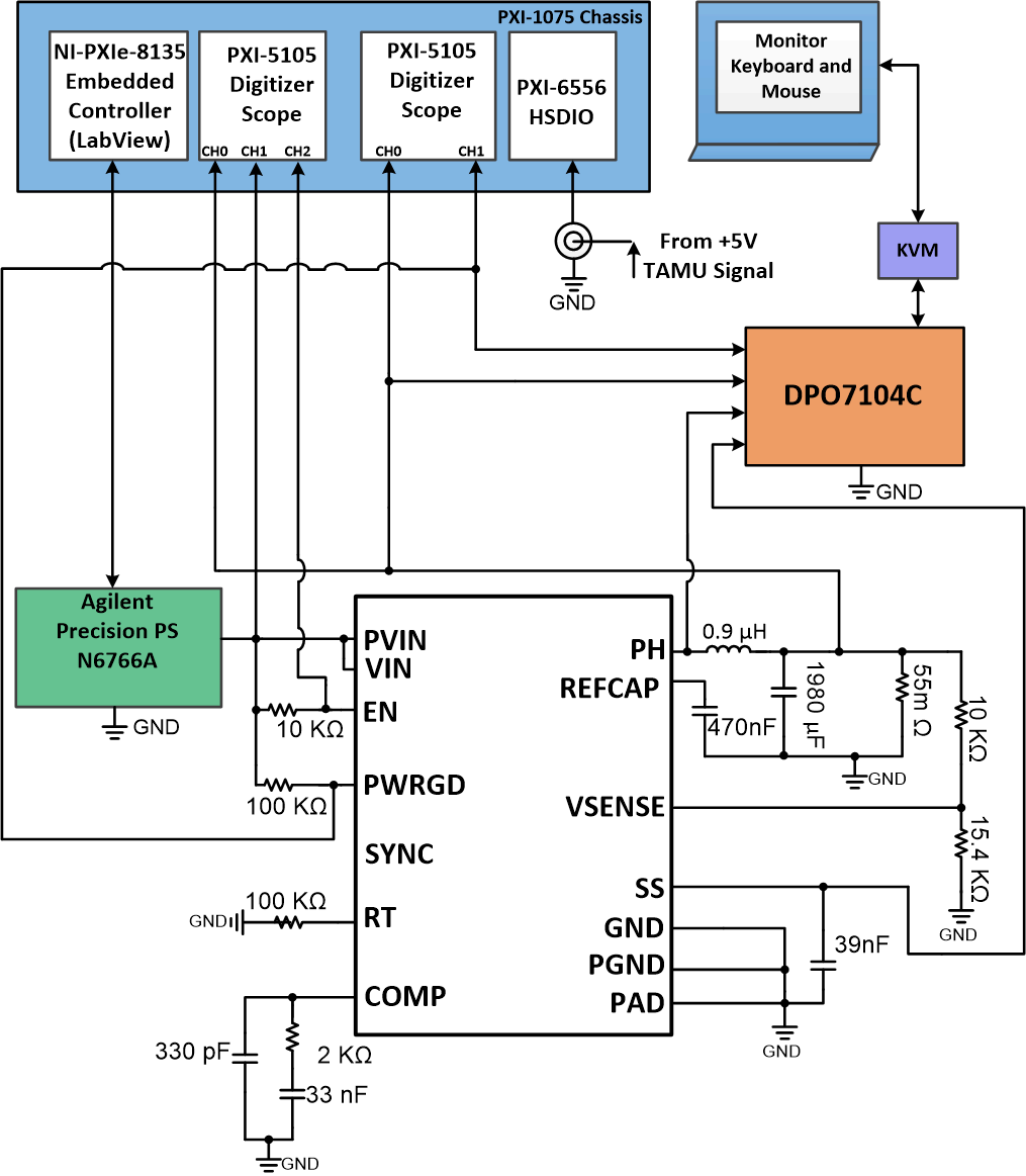
SEE testing was performed on a TPS7H4001-SP device mounted on a TPS7H4001SPEVM, 18-A, regulator evaluation module. Power was provided to the device by means of the PVIN input on the J2 connectors using the N6766A PS module mounted on a N6705 precision power supply in a 4-wire configuration. The PVIN and VIN were tied together using the R4 and R23 0-Ω resistors on the EVM. The device was loaded using a discrete power resistor of 55 mΩ dissipating 18 A (for most cases). For the case when the load was sweep to determine the load dependency on the DSEE a chroma electronic (model: 63630-80-80) load was used.
With the exception of the DPO digital oscilloscope, all equipment was controlled and monitored using a custom-developed LabVIEW® program (PXI-RadTest) running on a NI-PXIe-8135 Controller. A block diagram of the test setup used for SEE characterization of the TPS7H4001-SP is illustrated in Figure 6-1 .Connections, limits and compliance used are shown in Table 6-1. The TPS7H4001-SP was tested at 3 different temperature conditions as described below:
- T = 125°C used for all SEL testing. Temperature was achieved with the use of a convection heat gun aimed at the die.
- T = 20 to 31°C (disable/enabled) used for SEB/SEG testing. Achieved by using a vortex tube aimed at the die.
- Around 60°C (at 18 A, 7 V) for all SET characterization. Under this condition no external heat or cool element was used.
The die temperature was monitored during the testing using a K-Type thermocouple attached to the thermal pad vias (on the bottom side of the EVM) with thermal paste. The thermocouple was hold on place by using high temperature tape (kapton-tape). Die to thermocouple temperature was verified using a IR-camera, prior to the SEE test campaign.
| Pin Name | Equipment Used | Capability (A) | Compliance (A) | Value Used (V) |
|---|---|---|---|---|
| PVIN/VIN | N6766A | 15 | 10-15 | 5-7 |
|
Oscilloscope Card |
NI-PXIe 5105 |
60MS/s |
- |
20Ms/s |
|
Digital Phosphor Oscilloscope |
Tektronix DPO7104C |
40 GS/s |
- |
20MS/s - 2G S/s |
|
Digital I/O |
NI PXIe 6556 |
200 MHz |
- |
50 MHz |
All boards used for SEE testing were fully checked for functionality and dry runs performed to ensure that the test system was stable under all bias and load conditions prior to being taken to the TAMU facility. During the heavy-ion testing, the LabView control program powered up the TPS7H4001-SP device and set the external sourcing and monitoring functions of the external equipment. After functionality and stability had been confirmed, the beam shutter was opened to expose the device to the heavy-ion beam. The shutter remained open until the target fluence was achieved (determined by external detectors and counters), or a device was damaged. The current on the PVIN and VIN (tied-together for all test) was monitored at all times.
 Figure 6-1 Block Diagram of the SEE Test Setup for the TPS7H4001-SP