SLVAET3 October 2021 TPS8802
- Trademarks
- 1Introduction
- 2System Architecture
- 3Current Consumption
- 4System Power Calculation and Measurements
- 5Summary
- 6References
4.1.1 Power Consumption Overview Page
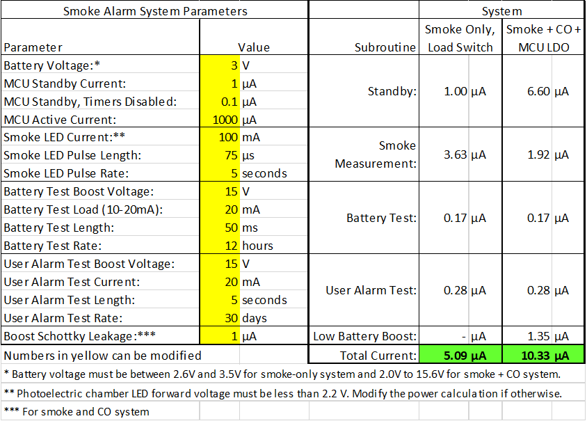
 Figure 4-1 Power Consumption Overview
The power calculation overview page highlights the key parameters that affect the power consumption. The current consumption for each subroutine is calculated, and by adding together each subroutine current, the total current is calculated. The detailed calculations for each subroutine total are performed in the Smoke and CO Power and Smoke Only Power pages.
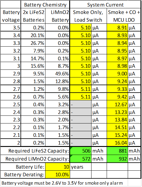
With the power calculated, the required battery life is then calculated. The result of the power calculation at each battery voltage is entered into the 3V Battery Life table shown in Figure 4-2. The table lists the percentage of a LiFeS2 and LiMnO2 battery capacity at each voltage. These capacity percentages are derived from battery manufacturer’s datasheets. The power consumption and capacity percentage data calculates the required battery capacity for a given battery life.
 Figure 4-2 Battery Life Calculation Table
Using a TPS8802 with a 1-µA standby current microcontroller (0.1 µA with timers disabled), 100-mA IR LED current, 75 µs IR LED pulse length, and 5 second measurement interval, the required battery capacity is calculated. The smoke and CO system achieves a 10 year battery life using a single CR123 battery (typical capacity 1500 mAh) with 61% margin or two lithium AAA batteries (typical capacity 1250 mAh) with 42% margin. The smoke-only system achieves a 10 year battery life using a single CR2 battery (typical capacity 800 mAh) with 40% margin.