SLVAET3 October 2021 TPS8802
- Trademarks
- 1Introduction
- 2System Architecture
- 3Current Consumption
- 4System Power Calculation and Measurements
- 5Summary
- 6References
3.3.2 Initialization Current
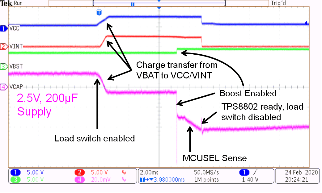
In systems where a load switch periodically applies power to VCC, power is dissipated during the TPS8802 initialization. The initialization current has several components: VCC charging, VINT charging, MCUSEL sensing, and VBST charging. The VCC, VINT, and VBST waveforms and battery current draw during the TPS8802 initialization are shown in Figure 3-1.
 Figure 3-1 TPS8802 Initialization Waveforms
The VCC and VINT capacitors are charged when the load switch is enabled. The amount of power required to charge these capacitors depends on the capacitance, voltage, and frequency of initialization. The MCUSEL pin is sensed during initialization to determine the default MCU LDO voltage. Sensing the MCUSEL pin typically draws 2.2 mA current for 1.2 ms. The initialization current is calculated in Equation 11.

The initialization current caused by boost charging depends on the charging frequency and VBST voltage change. During initialization, the boost converter is automatically enabled to 3.8 V with 500 mA peak inductor current. If VBST is below 3.8 V, the boost converter switches until VBST is above 3.8 V. If the VBST load is low between measurements, the boost converter does not switch during every initialization.
The VBST voltage change depends on the VBST load between measurements. The minimum VBST voltage change is the boost converter ripple, and the maximum VBST voltage change is VBST minus VBAT. In Figure 2-8, the only load on VBST between measurements is the Schottky diode leakage. Therefore the Schottky diode leakage has a large impact on the boost charge current. The boost converter ripple is calculated in Equation 12, the charging frequency is calculated in Equation 13, and the boost charging initialization current is calculated in Equation 14.


