SLVAEX3 October   2020 TPS8802 , TPS8804


  1.   Trademarks
  2. 1Introduction
  3. 2SNR Optimization
    1. 2.1 SNR Overview
    2. 2.2 Smoke Concentration Measurement
    3. 2.3 Amplifier and LED Settings
      1. 2.3.1 Photo Amplifier Gain
      2. 2.3.2 Photo Amplifier and AMUX Speed
      3. 2.3.3 LED Current and Pulse Width
    4. 2.4 ADC Sampling and Digital Filtering
      1. 2.4.1 ADC Sampling
      2. 2.4.2 Digital Filtering
  4. 3System Modeling
    1. 3.1 Impulse Response
      1. 3.1.1 Photodiode Input Amplifier Model
      2. 3.1.2 Photodiode Gain Amplifier and AMUX Buffer Model
      3. 3.1.3 Combined Signal Chain
    2. 3.2 Noise Modeling
      1. 3.2.1 Noise Sources
      2. 3.2.2 Output Voltage Noise Model
      3. 3.2.3 ADC Quantization Noise
    3. 3.3 SNR Calculation
      1. 3.3.1 Single ADC Sample
      2. 3.3.2 Two ADC Samples
      3. 3.3.3 Multiple Base ADC Samples
      4. 3.3.4 Multiple Top ADC Samples
      5. 3.3.5 Multiple ADC Sample Simulation
  5. 4SNR Measurements
    1. 4.1 Measurement Procedure
    2. 4.2 Measurement Processing
    3. 4.3 Measurement Results
      1. 4.3.1 Varying Amplifier Speeds
      2. 4.3.2 Varying Digital Filter and ADC Timing
      3. 4.3.3 Varying LED Pulse Length
      4. 4.3.4 Varying ADC Sample Rate
      5. 4.3.5 Real and Ideal System Conditions
      6. 4.3.6 Number of Base Samples
      7. 4.3.7 ADC Resolution
  6. 5Summary
  7. 6References

Multiple ADC Sample Simulation

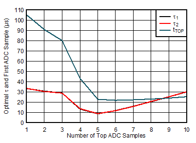
A simulation of the smoke measurement system is implemented in MATLAB. A nonlinear programming solver, fminsearch, optimizes the ADC timing, amplifier time constants, and unconstrained filter weights. The result of the optimization for a 100 μs LED pulse and 20 μs ADC sampling rate is shown in Figure 3-5. The average and matched filter have initial parameters of τ1 and τ2 set to 0.31 times tLED and the ADC samples centered on tLED. Unconstrained filtering improves the SNR the most, by 6%, followed by matched filtering and average filtering at 4%. Each filter type also has a trend: as the number of ADC samples increases, the optimal τ1 and τ2 decreases, as shown in Figure 3-6. These trends are visible in the measurements as shown in Section 4.

GUID-20200929-CA0I-Z9J6-0JJF-TJVTJWNHVLC1-low.gif

tLED=100 µs tSAMP=20 µs

Figure 3-5 Comparison of Simulated Digital Processing Methods
GUID-20200929-CA0I-RCVL-DNXF-ZRPLDV72HSGT-low.gif

tLED=100 µs tSAMP=20 µs

Figure 3-6 Simulated Optimal Averaging Filter Parameters