SLVAEX4A January 2021 – May 2021 TPS272C45
3 Using the SPI Expander with the TPS272C45EVM
This application note comes with a referenced ZIP file that contains the hardware gerber files and BOM as well as an example software implementation of the SPI expander for the SimpleLink CC2652 wireless microcontroller.. The gerber files and BOM are located in the gerbers directory of the attached ZIP file and are separated into two different folders for the SPI expander and daughter card attachment. The software folder contains a sample software implementation that can control the SPI expander board via the CC2652R's SPI peripheral with a serial port terminal connection.
The sample application provided is a simple application that lets the user control the SPI expander board from the onboard serial port attached to the LAUNCHXL-CC26X2R1 LaunchPad. It is recommended to use a serial port application such as PuTTY or TeraTerm for serial port communication. The serial port settings can be seen below in Figure 3-1.
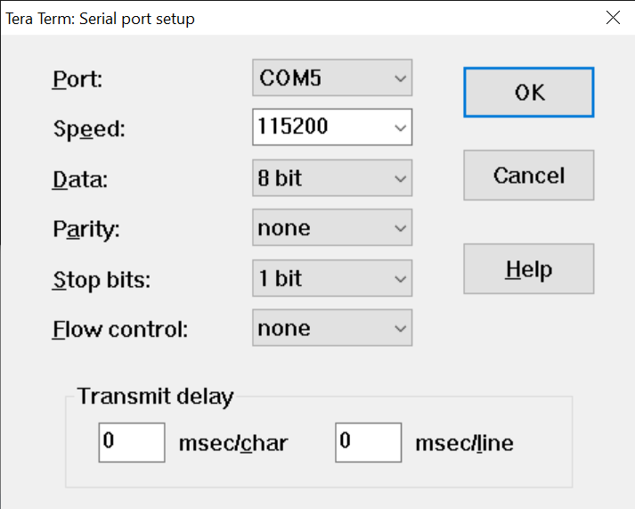 Figure 3-1 Serial Port Settings
When the spi_expander_test.out binary is flashed onto the LaunchPad using Uniflash, open the serial port program of your choice. Make sure to open the appropriate serial port terminal marked as the Application/User serial port in your serial terminal program such as shown in Figure 3-2.
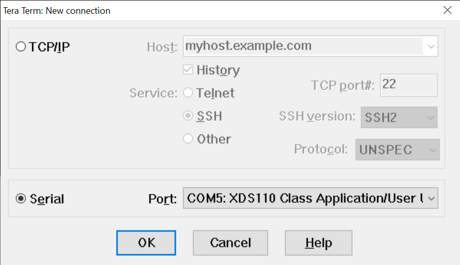 Figure 3-2 User/Application UART
Once connected to your serial port and the program has been flashed onto the CC2652R press the RESET button on top of the LaunchPad. The following menu print on the serial terminal appears as shown in Figure 3-3.
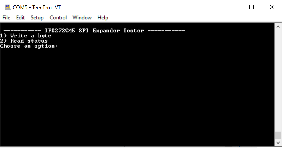 Figure 3-3 Main Menu
The serial port in this application has the ability to take in user input as well as display the status of the SPI expander. From the main menu enter 1 to write a word of data. You will then be prompted to enter four hexadecimal characters that represent the 16-bit word of the ENx lines that you want to toggle. In Figure 3-4, we enter CAFE to write the hexadecimal value 0xCAFE to the SPI expander.
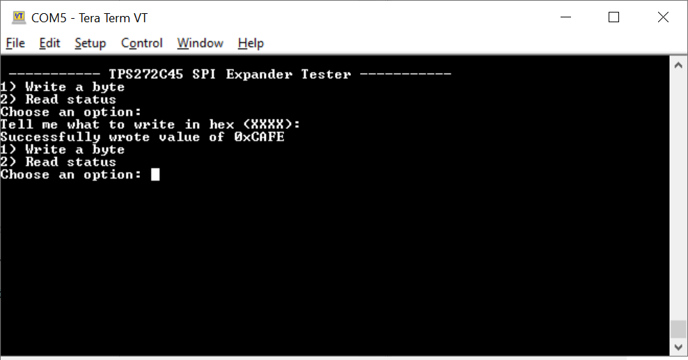 Figure 3-4 Writing 0xCAFE
From an attached logic analyzer in Figure 3-5, you can see the relevant bytes being written over the SPI bus on the CC2652R LaunchPad as well as the relevant ENx bits being enabled/disabled.
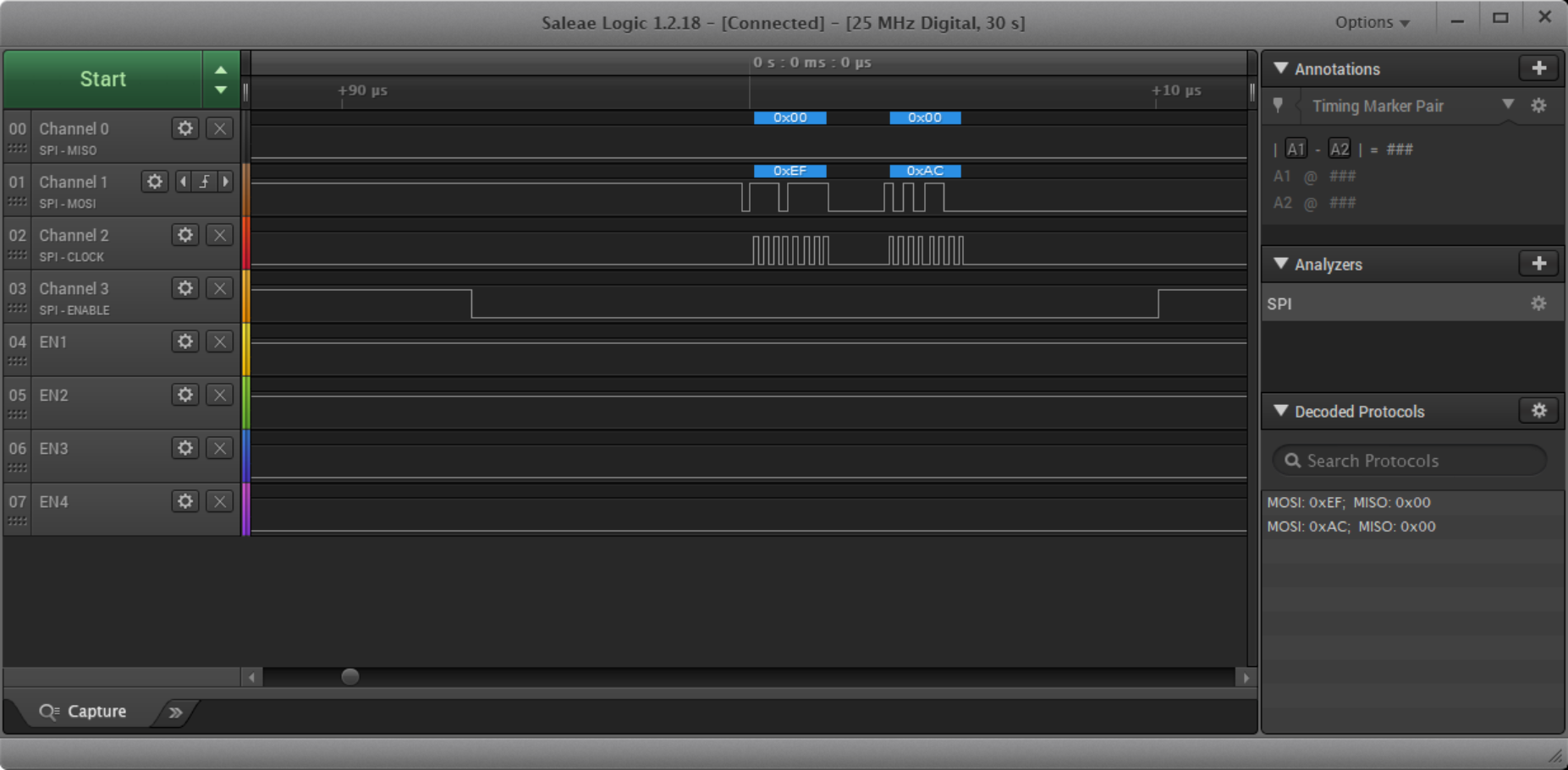 Figure 3-5 SPI Transaction - Writing to
ENx
Figure 3-5 SPI Transaction - Writing to
ENxWith the TPS272C45EVMs attached to the daughter card this toggles on and off the load connected to the corresponding VOUT1 and VOUT2 channels. Note that the bit order of the write has been reversed to match the pin out of the daughter card as well as the bit order of the attached shift registers. Also note that as SPI is full duplex that both the ENx and FLTx lines are written/read at the same time. When performing a polling transaction to read the FLTx lines it is necessary to also write the appropriate ENx lines so that those bits do not get reset. This can be prevented by having separate SPI CS lines for both the FLTx and ENx shift registers on the schematic (at the expense of an additional GPIO on the microcontroller). The code block for reading the FLTx lines (and by effect writing the ENx lines) can be found below from spi_expander_test.c.
            /* Reading/Writing the SPI registers */
            transaction.count = 2;
            transaction.txBuf = &writeByteReversed;
            transaction.rxBuf = &readByte;

            GPIO_write(SPI_EXPANDER_CS, 0);
            retCode = SPI_transfer(masterSpi, &transaction);
            GPIO_write(SPI_EXPANDER_CS, 1);

            if(retCode == true)
            {
                terminalWrite("\r\nSuccessfully read value of ");
                sprintf(readByteString, "0x%X", (readByte & 0xFF));
                terminalWrite(readByteString);
                terminalWrite("\r\n");
            }
            else
            {
                terminalWrite("\r\nError reading byte value!!!\r\n");
            }
For illustration, a fault was artificially introduced into the SPI expander by tying the FLT1 and FLT2 pins to the 3.3 V rail on the LaunchPad. When the SPI transaction above is now performed, a value of 0x03 can be read from the FLT shift register representing a fault on channel 1 and channel 2 of the first TPS272C45EVM.
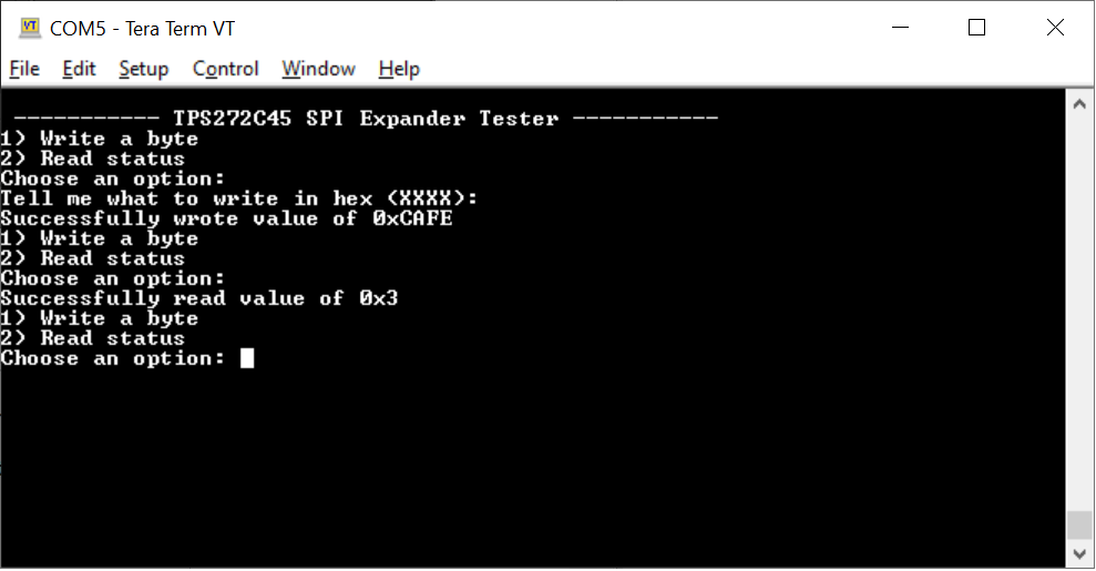 Figure 3-6 Reading a Fault
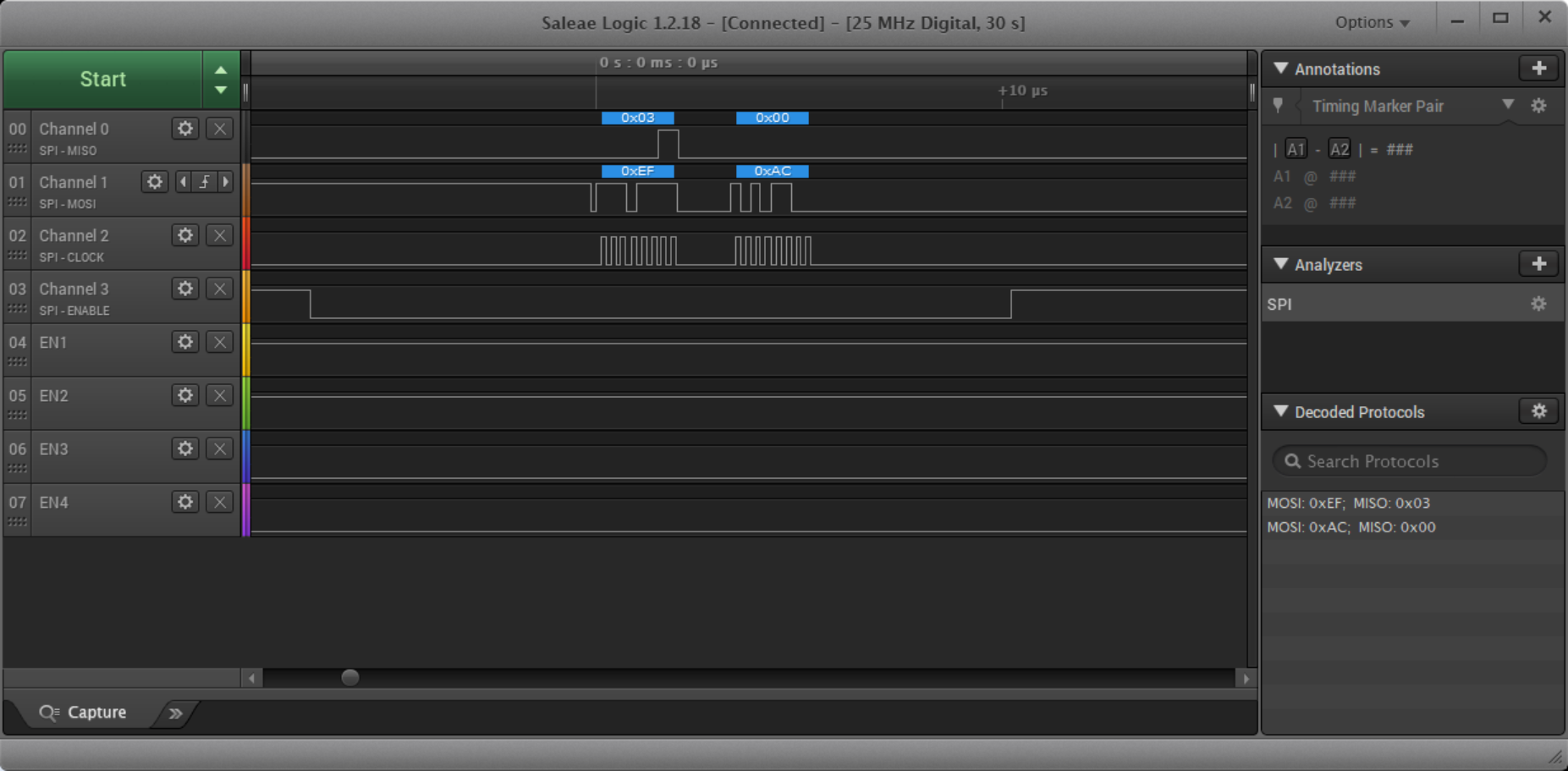 Figure 3-7 Fault on SPI Line
As two bytes are read by the SPI master to match the byte length for the read it is the responsibility of the application to mask out the irrelevant bytes in software. In the example above we take the 16-bit value read by the microcontroller for the FLTx line and bitwise AND it with 0xFF to get the relevant data.