SLVAEX4A January 2021 – May 2021 TPS272C45
2 Connecting the SPI Expander to the TPS272C45EVM
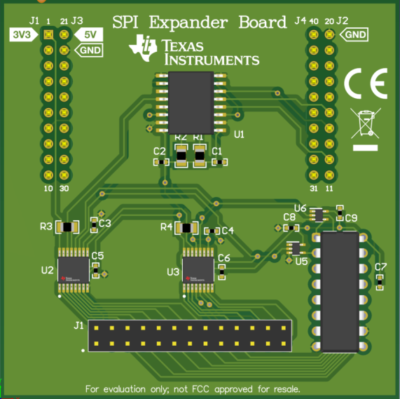
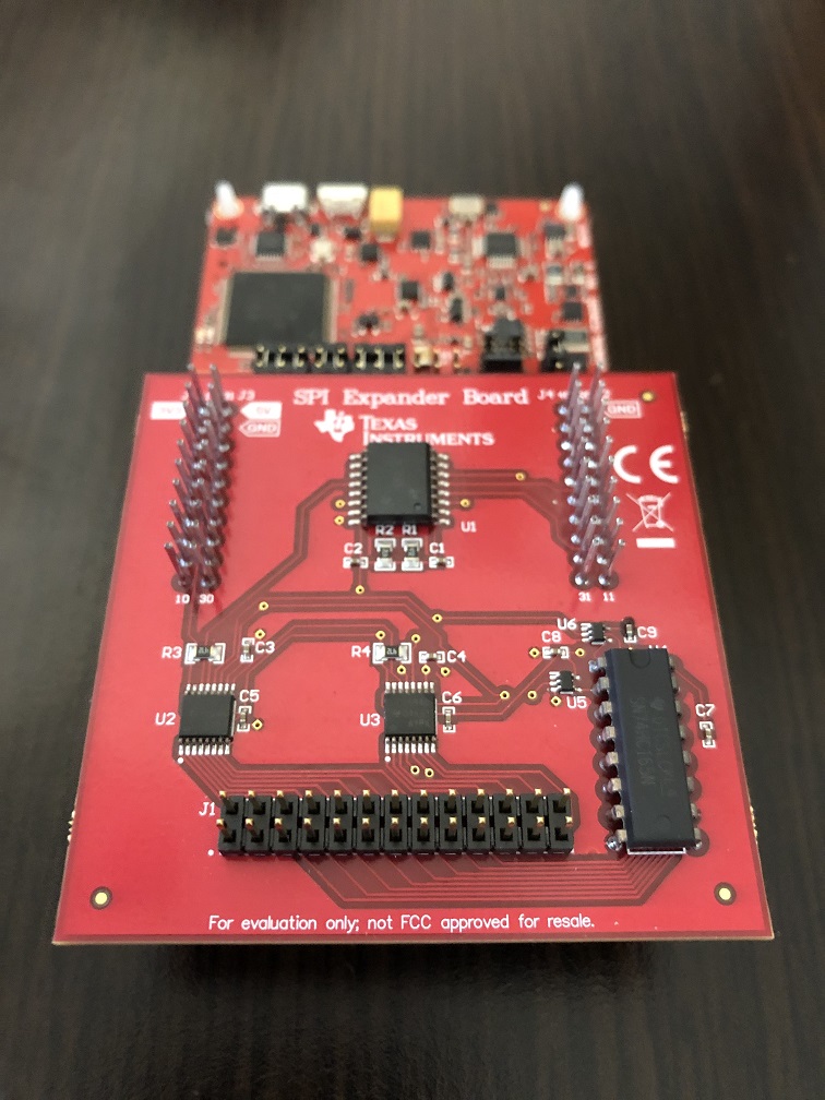
The reference implementation provided with this application note contains two different hardware components: a SPI expander board and an attachable daughter card. The expander board is designed to be connected directly to the SPI master (normally a microcontroller) and contains all of the necessary shift registers and isolators required for SPI communication. Additionally the SPI expander board is populated with BoosterPack headers allowing for easy interfacing with a Texas Instruments LaunchPad based microcontroller. A picture of the SPI expander board can be seen below in Figure 2-1 and a picture of the SPI expander connected to a LAUNCHXL-CC26X2R1 can be seen in Figure 2-2.
 Figure 2-1 SPI Expander Board
 Figure 2-2 SPI Expander and
LAUNCHXL-CC26X2R1
Figure 2-2 SPI Expander and
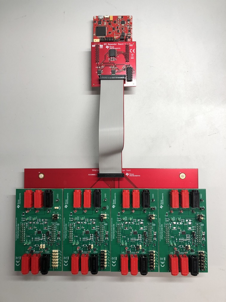
LAUNCHXL-CC26X2R1The daughter card implementation attached is a breakout board designed to be connected to the SPI expander board via standard 2x13 ribbon cable. The breakout board has four separate BoosterPack headers used to connect four separate TPS272C45EVMs. A picture of the completed SPI expander + daughter card + 4 x TPS272C45EVM solutions can be seen below in Figure 2-3.
 Figure 2-3 Connected SPI Expander
Note that the function of the 2x13 ribbon cable is to relay the FLTx and ENx signals from the TPS272C45EVMs on the daughter card to the SPI expander board. Take care to make sure that the relevant PIN1 of the ribbon cable on the SPI expander matches that of the PIN1 header on the daughter card as shown in the picture above. The pinout for the ribbon cable header on the main SPI expander board can be seen below in Figure 2-4.
 Figure 2-4 Pinout for SPI Expander
Board