SLVAEZ4 June 2021 TPS272C45
2 Current Sense
The TPS272C45 high-side switch features a high accuracy current sense capability that can be used to detect granular variations on load current. The current sense block of the TPS272C45 outputs a reference current to the SNS pin that is a scaled down representation of the current on the load. This current is translated to a voltage through an attached SNS resistor and read by the ADC of the microcontroller.
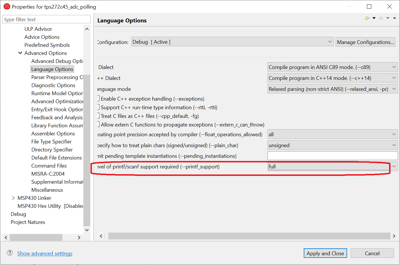
In the tps272c45_adc_polling code example provided with this application the current of channel 1 (VOUT1) is polled at an interval of 500mS and the result is displayed through the debug terminal of the MSP-EXP430F5529LP. The raw ADC value is passed into the debugger's printf statement and displayed on the debug terminal through Code Composer Studio. Note that for the print statements to work correctly, printf support must be enabled in the compiler options as shown in Figure 2-1.
 Figure 2-1 Compiler Option for printf
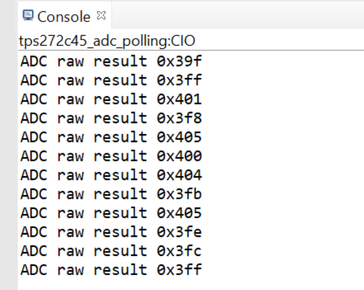
Once connected, press the S1 button on the top of the MSP-EXP430F5529LP to assert the EN1 signal high and enable the output on VOUT1. When the channel is enabled, a timer will start on the microcontroller and periodically sample/convert the voltage on the SNS pin, record the result, and then display the result through the debugger screen. The output of this code example is shown in Figure 2-2.
 Figure 2-2 Console Print with ADC
Results
Figure 2-2 Console Print with ADC
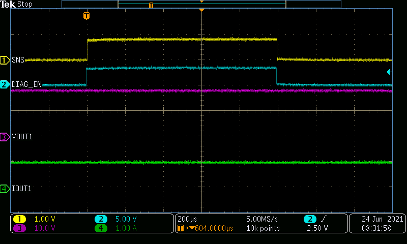
ResultsOne important aspect to note about a polling based approach for measuring the current is the behavior of the DIAG_EN pin on the TPS272C45. The DIA_EN pin will enable or disable the current sensing block on the TPS272C45. As a result the power consumption of the TPS272C45 will be significantly higher when DIAG_EN is high versus low. For this reason it is recommended only to assert the DIAG_EN signal high right before the ADC sample/conversion and assert it low immediately after. Note that from the time it takes from the initial rising edge of DIAG_EN to when the SNS signal has settled is specified in the data sheet as tSNSION1. This value must be taken into account in the software through a delay to sample an accurate reading on the ADC. The relevant software code snippet is shown in Figure 2-3 with an oscilloscope screen shot of the DIAG_EN and SNS pin.
        /* Enabling the diagnostic block and delaying */
        DIA_EN_OUT |= DIA_EN_PIN;
        __delay_cycles(1000);

        /* Starting the conversion */
        ADC12CTL0 |= ADC12SC;

        /* Waiting for the interrupt */
        __bis_SR_register(LPM0_bits + GIE);

        /* Disabling diagnostic block */
        DIA_EN_OUT &= ~DIA_EN_PIN;

        /* Set breakpoint here to record result */
        __no_operation();
        printf("\nADC raw result 0x%x", adcConvRes);

        /* Delaying between measurements */
        __delay_cycles(1000000);
Figure 2-3 Current Sense with DIAG_EN
Toggling
Figure 2-3 Current Sense with DIAG_EN
TogglingThe tps272c45_comparator code example connects the output of the SNS pin to one of the MSP430's integrated fast comparator peripherals. This can be used as a signal monitor to continuously monitor the output current of the TPS272C45 and quickly trip when a threshold is crossed. This can either be used to quickly detect an undercurrent event by setting the comparator to trip on a falling edge or to provide a current limit pre-warning interrupt to the microcontroller when the comparator is configured to interrupt on a rising edge.
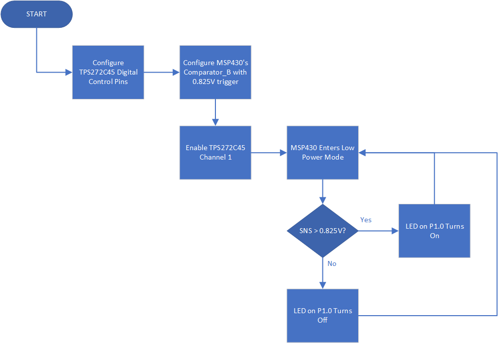
In this code example, the output of the SNS pin is connected to one of the MSP430's internal quick comparators and configured to fire an interrupt when the output load current exceeds 1-A on VOUT1. Once this interrupt fires the LED on the MSP-EXP430F5529LP will turn on to signify the event. As with previous code examples, the S1 button on the side of the LaunchPad is used to turn on and off VOUT1. For simplicity, all fault reporting and error handling has been removed from this code example. This behavior is shown in Figure 2-4.
 Figure 2-4 Comparator Flow Chart
Note that unlike the ADC polling example, for the comparator example to work, the DIAG_EN line must be either continuously enabled or periodically enabled long enough for the current sense to register a correct reading. This code example assumes that the power budget is not a big factor in the application and leaves the DIAG_EN line enabled through the entire program; however software optimizations such as DMA utilization could be adopted to automatically toggle the DIAG_EN line from a hardware timer.