SLVAF41A March 2021 – November 2021 TPS61094
6.1 Test Waveform
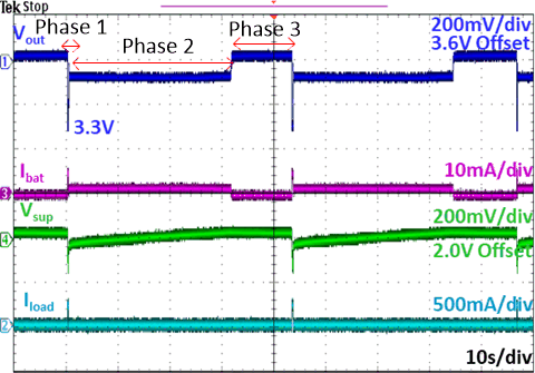
The TPS61094 with supercap solution test waveform overview is as shown in the Figure 6-1. There are three phases in this solution. Phase 1 is the NB-IoT data transmission. The load current is about 250 mA for 250 ms. The TPS61094 could regulate output voltage to 3.3 V and control the battery current within 5 mA. In the phase 2, the NB-IoT stops doing the data transmission, so TPS61094 charges the supercap in setting current about 2.5 mA. As shown in the Figure 6-1, the supercap voltage increases and triggers charging terminal voltage (2 V). The TPS61094 stops charging and this is phases 3. The whole system enters the standby mode and waits for the next NB-IoT transmission.
 Figure 6-1 The Performance Overview of
the TPS61094 with Supercap Solution
Figure 6-1 The Performance Overview of
the TPS61094 with Supercap SolutionNote:
The dark blue signal (Channel 1) is TPS61094 output voltage, The purple signal(Channel 1) is LiSOCl2 battery output current, The green signal(Channel 4) is the supercap voltage, The light blue signal(Channel 2) is load current.