SLVAFE5 September 2022 TPS92610-Q1 , TPS92611-Q1 , TPS92612-Q1 , TPS92613-Q1
2.4 Fault Detection Logic Summary
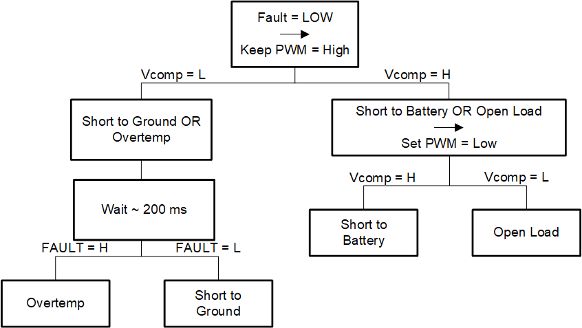
Figure 2-7 illustrates final flow of logic of the fault detection circuit.
 Figure 2-7 Discrete Fault Detection Logic
Flowchart
Figure 2-7 Discrete Fault Detection Logic
FlowchartAs Figure 2-7 shows, the comparator output (Vcomp), is used to distinguish if a SG, OT or SB, OL has occurred. If a SB or OL has occurred, Vcomp can be used to further distinguish between the two after PWM is pulled LOW. For SG, OT conditions, the fault pin is used along with the PWM pin to distinguish between a SG or OT fault.