SLVAFE5 September 2022 TPS92610-Q1 , TPS92611-Q1 , TPS92612-Q1 , TPS92613-Q1
3.1 Simulation
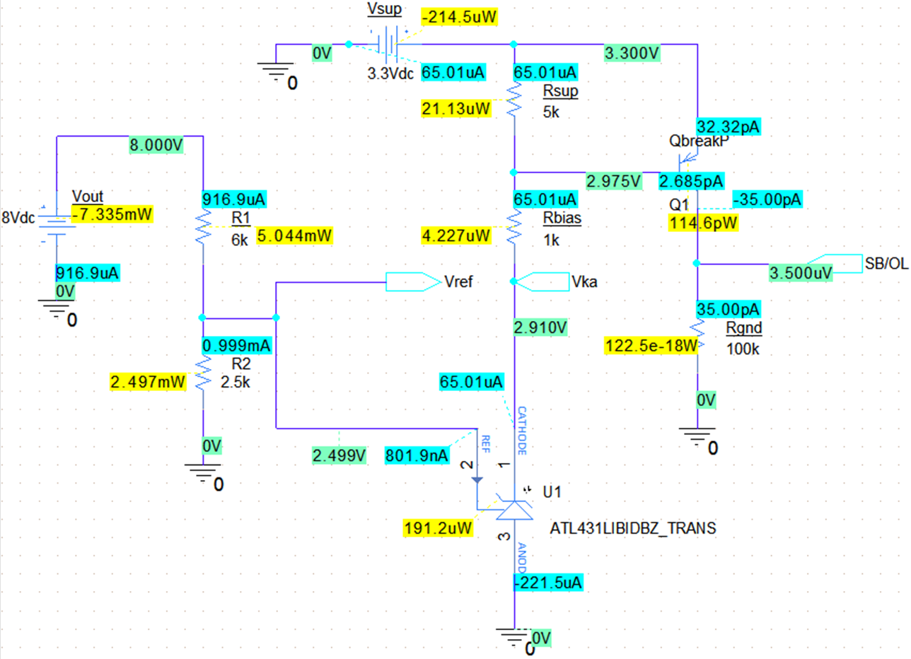
The fault detection circuit was created on PSpice® and an independent voltage source was used to simulate different voltage conditions on the TPS9261x-Q1 output. Figure 3-2 shows the circuit when the TPS9261x-Q1 output voltage is below the trip point of 8.5 V.
 Figure 3-2 Simulation With TPS9261x-Q1
Vout Below the Trip Point
Figure 3-2 Simulation With TPS9261x-Q1
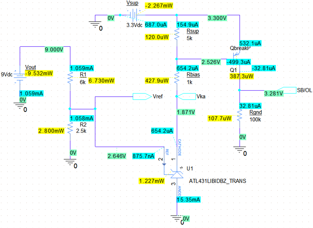
Vout Below the Trip PointAn 8-V voltage was applied to the fault detection circuit and with accordance to the truth table in Table 3-1. A proper LOW output is shown at SB/OL. Figure 3-3 shows the circuit when a voltage above the trip point of 8.5 V is present.
 Figure 3-3 Simulation With TPS9261x-Q1
Vout Above the Trip Point
Figure 3-3 Simulation With TPS9261x-Q1
Vout Above the Trip PointA voltage of 9 V was applied to the fault detection circuit and with accordance to Table 3-1 the Vcomp output is HIGH as shown on SB/OL.