SLVAFE5 September 2022 TPS92610-Q1 , TPS92611-Q1 , TPS92612-Q1 , TPS92613-Q1
3 Discrete Fault Detection Circuit Details
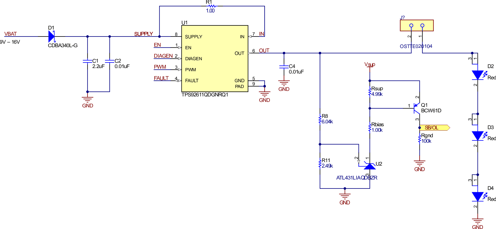
The discrete fault detection circuit utilizes the ATL431LI-Q1 device as a comparator to monitor the TPS9261x-Q1 output voltage. The ATL431LI-Q1 is a high bandwidth low IQ programmable shunt regulator that can act as a comparator in open loop mode. Additionally, the device has an internal reference voltage of 2.5 V and works well across temperature providing an accurate output voltage measurement. For more information on the ALT431LI-Q1 performance across temperature, see Using the TL431 for Undervoltage and Overvoltage Detection application note. The ATL431LI-Q1 output (Vcomp) is used to differentiate between OL, SB, and SG or OT conditions. Figure 3-1 illustrates the initial schematic with the fault detection circuit added on to the TPS9261x-Q1.
 Figure 3-1 Discrete Fault Detection
Schematic
Figure 3-1 Discrete Fault Detection
SchematicA resistor divider must be used to properly divide the voltage going into the ATL431LI-Q1 from the output of the TPS9261x-Q1. This is to properly compare the OUT voltage to the reference voltage. In addition, this resistor ladder creates the trip point (where the comparator output changes). A trip point of 8.5 V was used for the tests in Section 3.1 to Section 3.4. To verify the resistor ladder behaves as expected, the total series resistance (Rtotal) of the resistive divider R8 and R11 must be approximately 8.5 kΩ. Due to the I(retry), a Rtotal that is too large causes the output and input voltages to be close to equal and therefore the ATL431LI-Q1 comparator does not trigger. Rsup and Rbias are used in accordance to Using the TL431 for Undervoltage and Overvoltage Detection application note to verify that the BJT has an appropriate voltage drop and that the ATL431LI-Q1 is not sinking excess current. Rgnd is utilized to pullup the SB, OL output to Vsup. Additionally, a BJT is used to verify that the ATL431LI-Q1 output swings from Vsup (3.3 V) to 0 V as described in the previously-referenced application note. Table 3-1 documents the logic truth table associated with the fault detection circuit. Each unique outcome is highlighted to show the logic for a microcontroller to differentiate between each fault scenario.
|
Condition |
PWM |
nFault |
Comparator Output (Vcomp) |
|---|---|---|---|
|
Normal Operation |
L |
H |
L |
|
H |
H |
L |
|
|
Short to GND, Over Temperature |
L |
L |
L |
|
H |
L |
L |
|
|
Short to Vbat |
L |
L |
H |
|
H |
L |
H |
|
|
Open Load |
L |
H |
L |
|
H |
L |
H |