SLVS417F March   2002  – June 2015 TPS62200 , TPS62201 , TPS62202 , TPS62203 , TPS62204 , TPS62205 , TPS62207 , TPS62208

PRODUCTION DATA.  

  1. Features
  2. Applications
  3. Description
  4. Revision History
  5. Pin Configuration and Functions
  6. Specifications
    1. 6.1 Absolute Maximum Ratings
    2. 6.2 ESD Ratings
    3. 6.3 Recommended Operating Conditions
    4. 6.4 Thermal Information
    5. 6.5 Electrical Characteristics
    6. 6.6 Typical Characteristics
  7. Detailed Description
    1. 7.1 Overview
    2. 7.2 Functional Block Diagram
    3. 7.3 Feature Description
      1. 7.3.1 Undervoltage Lockout
      2. 7.3.2 Dynamic Voltage Positioning
      3. 7.3.3 Soft Start
      4. 7.3.4 Low Dropout Operation 100% Duty Cycle
      5. 7.3.5 Enable
    4. 7.4 Device Functional Modes
      1. 7.4.1 Power Save Mode Operation
  8. Application and Implementation
    1. 8.1 Application Information
    2. 8.2 Typical Application
      1. 8.2.1 Design Requirements
      2. 8.2.2 Detailed Design Procedure
        1. 8.2.2.1 Adjustable Output Voltage Version
        2. 8.2.2.2 Inductor Selection
        3. 8.2.2.3 Input Capacitor Selection
        4. 8.2.2.4 Output Capacitor Selection
      3. 8.2.3 Application Curves
    3. 8.3 System Examples
      1. 8.3.1 Various Output Voltages
      2. 8.3.2 Adjustable Output Voltage Version Set to 1.5 V
  9. Power Supply Recommendations
  10. 10Layout
    1. 10.1 Layout Guidelines
    2. 10.2 Layout Example
  11. 11Device and Documentation Support
    1. 11.1 Device Support
      1. 11.1.1 Third-Party Products Disclaimer
    2. 11.2 Related Links
    3. 11.3 Community Resources
    4. 11.4 Trademarks
    5. 11.5 Electrostatic Discharge Caution
    6. 11.6 Glossary
  12. 12Mechanical, Packaging, and Orderable Information

10 Layout

10.1 Layout Guidelines

  • For all switching power supplies, the layout is an important step in the design, especially at high peak currents and switching frequencies. If the layout is not carefully done, the regulator shows stability problems as well as EMI problems.
  • Therefore use wide and short traces for the main current paths, as indicated in bold in Figure 19. The input capacitor should be placed as close as possible to the IC pins.
  • The feedback resistor network must be routed away from the inductor and switch node to minimize noise and magnetic interference. To further minimize noise from coupling into the feedback network and feedback pin, the ground plane or ground traces must be used for shielding. This becomes very important especially at high switching frequencies of 1 MHz.

10.2 Layout Example
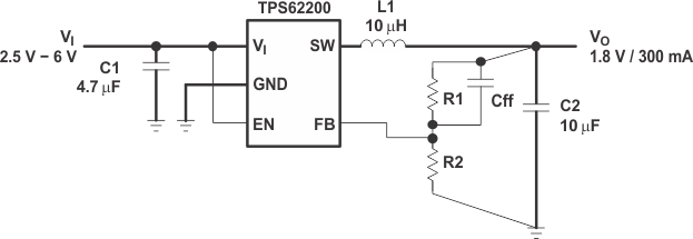
TPS62200 TPS62201 TPS62202 TPS62203 TPS62204 TPS62205 TPS62207 TPS62208 ai_dia_lvs417.gifFigure 19. Layout Diagram