SLVU240B May   2008  – August 2018 MSP430F2131 , TPS62260


  1.   Read This First
    1.     About This Manual
    2.     How to Use This Manual
    3.     Information About Cautions and Warnings
    4.     Related Documentation From Texas Instruments
    5.     If You Need Assistance
    6.     Trademarks
  2. 1Introduction
    1. 1.1 Requirements
      1. 1.1.1 Power Supply Requirements
      2. 1.1.2 Printed Circuit Board Assemblies (PCBs)
  3. 2Setup
    1. 2.1 Input/Output Connector Descriptions
      1. 2.1.1 J1, J2, and J3 – Power Supply Connectors
      2. 2.1.2 JP1 – Wireless Interface Connector
      3. 2.1.3 JP2 – JTAG Interface Connector
    2. 2.2 Hardware Setup
  4. 3Supported Colors and Operation Modes
    1. 3.1 Color Range
    2. 3.2 Auto-Scroll Mode
    3. 3.3 Manual Control Mode
  5. 4Design Description
    1. 4.1 Hardware Design
      1. 4.1.1 LED Power Stages
      2. 4.1.2 Output Filter Design
      3. 4.1.3 MODE and EN Pins
      4. 4.1.4 MSP430 MCU Design
    2. 4.2 LED Color Table
    3. 4.3 Firmware Design
      1. 4.3.1 Firmware C-Code Listing
  6. 5Schematic and Bill of Materials
    1. 5.1 Schematics
    2. 5.2 Bill of Materials
  7. 6Board Layout
    1. 6.1 Photographs of Top and Bottom
    2. 6.2 Layout
    3. 6.3 Thermal Images
  8. AReprogramming
    1. A.1 Additional Software and Hardware Needed
    2. A.2 IAR Embedded Workbench KickStart Software Installation
    3. A.3 Hardware Installation
    4. A.4 Using IAR Embedded Workbench to Download Code on MSP430 MCUs
  9.   Revision History

Manual Control Mode

The EVM leaves auto-scroll mode and enters manual control mode the first time the rotary control is activated. In manual control mode, the color balance of the three LEDs is adjusted by the user turning the rotary encoder S1. The faster the encoder is turned, the faster the colors transition from one to another; the direction of rotation determines whether the EVM traces the color triangle in Figure 3-1 clockwise or counterclockwise.
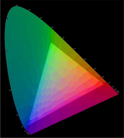
ciechrom_lvu240.gifFigure 3-1 CIE Chromaticity Diagram