SLVU240B May 2008 – August 2018 MSP430F2131 , TPS62260
6.3 Thermal Images
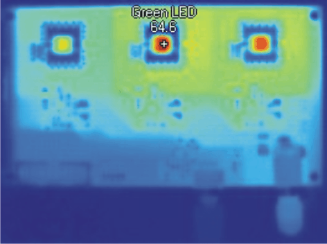
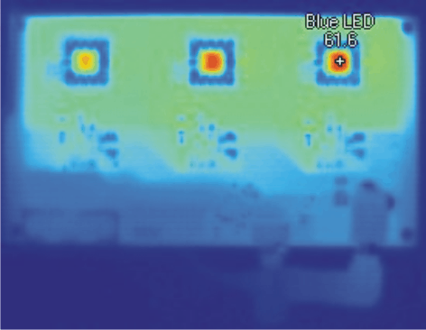
Figure 6-6 and Figure 6-7 show the thermal images of two EVM boards. The image in Figure 6-6 was obtained without using a heatsink and the image in Figure 6-7 with a heatsink mounted on the bottom of the PCB. Using a heatsink not only reduces the operating temperature of each LED, it also helps significantly to spread the heat more evenly.
These images were obtained using modified firmware that forced all three LEDs to operate with a 100% dimming duty cycle, meaning that they are fully on. Using the standard firmware, each LED is on for only one third of the time and off for two thirds of the time. As a result, the heat dissipation during normal use with the standard firmware is significantly lower than in this test case.
The heatsink used was SK 477 100 fixed with the thermally conductive foil WLFT 404 R25 both from Fischer Elektronik.
 Figure 6-6 EVM Without Heatsink
  Figure 6-7 EVM With Heatsink