SLVU876A February 2013 – May 2021 TPS65279V
5.5 Software Operation
This section provides descriptions of the EVM software.
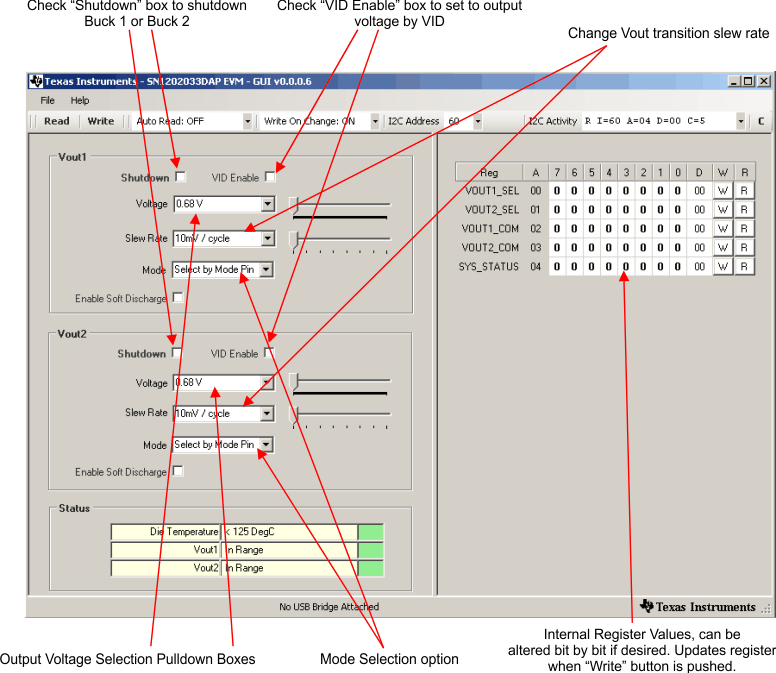
The supplied software is used to communicate with the TPS65279V EVM. Click on the icon on the host computer to start the software. The software displays the main control panel for the user interface (Figure 5-3).
 Figure 5-3 Screen Capture of TPS65279V Software GUI Interface
Figure 5-3 shows the GUI control interface. There are five 8-bit registers embedded in TPS65279V, two to select the output voltage, two to configure the buck converter’s operation, and one for status feedback. Changes are made by selecting and checking the components in the GUI on the left hand side and can also be made by directly clicking the bits of each register. I2C address is set to default 0x60H, this address is corresponding to the EVM jumper JP7 to connect to GND. Changing the I2C address requires that the EVM be configured accordingly.
An option is to “write on change”, if this option is set to ON, any change is sent to the EVM immediately; if this option is set to OFF, “Write” button or “W” button for each register must be clicked to send the control signal.
Register values can be read back from the EVM by clicking “Read” or “R” for each register.