SLVUBH1 September 2018
3.3.2.3 Bank Management
For most LED-animation effects, like blinking and breathing, all the RGB LEDs have the same lighting pattern. Instead of controlling the individual LED separately, which occupies the microcontroller resources heavily, the LP50xx device provides an easy coding approach, the LED bank control. Each channel can be configured as either independent control or bank control through the LEDx_Bank_EN register. When LEDx_Bank_EN = 0 (default), the LED is controlled independently by the related color-mixing and intensity-control registers. When LEDx_Bank_EN = 1, the LP50xx device drives the LED in LED bank-control mode. The LED bank has its own independent PWM control scheme, which is the same structure as the PWM scheme of each channel. See the register map Figure 14 for more details. When a channel is configured in LED bank-control mode, the related color mixing and intensity control is governed by the bank control registers (BANK_A_COLOR, BANK_B_COLOR, BANK_C_COLOR, and BANK_BRIGHTNESS) regardless of the inputs on its own color-mixing and intensity-control registers.
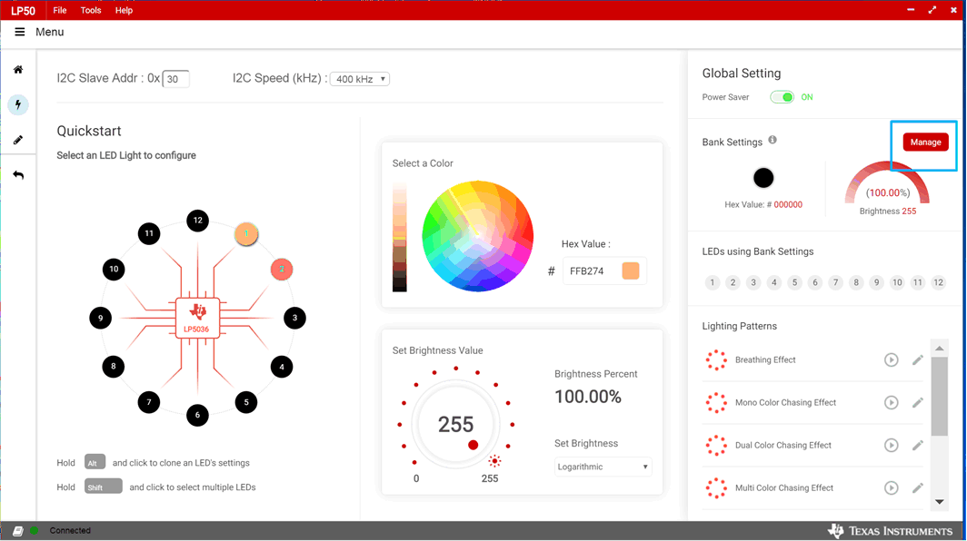
 Figure 11. Bank Management Entry
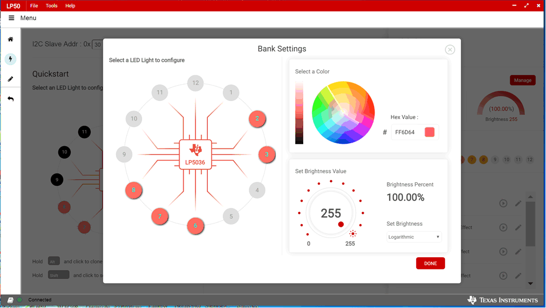
  Figure 12. Bank Setting