SLVUBW7 May 2020
- TPS7H4001QEVM-CVAL Evaluation Module User's Guide
8 Appendix A
The TPS7H4001EVM-CVAL hardware contains a sub-circuit which is useful when one wants to capture the transient response to a very high current step. For ‘low’ current transient steps, say less than 15 Amps, the response can be measured by simply switching the electronic load (e-load) between two currents states. However, the need exists to measure larger current step sizes when POLs are operating in parallel configurations. This poses a problem for this measurement technique as the inductance in the wire leads to the e-load causes undesirable spikes in the response. This problem is solved through the use of a transient sub-circuit that is provided on the EVM.
Figure 35 shows the schematic for this transient circuit. A power MOSEFT provided by Texas Instruments at Q1 is used to momentarily press the regulated VOUT voltage across power resistors R36 by modulating the gate of Q1 at TP29 with low duty cycle square wave.
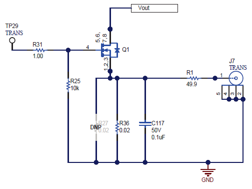 Figure 35. Transient Sub-circuit on the TPS7H4001QEVM-CVAL
 Figure 36 shows an overview of the setup for measuring the transient resposne to a high current step.
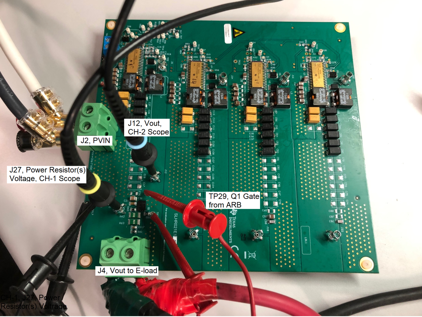 Figure 36. Setup for Measuring Transient Response to High Current Load Step
 The transient current step size is determined as follows:

With VOUT= 1.0V, Rdson_Q1 = 3.6 mohms (per data sheet), R36 = 20 mohms, R27=DNI, the calculated current step response is ~42.4 A. Eliminating the uncertainty of Rdson in the calculation is possible by capturing the actual voltage at probe testpoint J7 and dividing by the power resistance.

The key to a successful measurement (i.e. one without a smoking resistor), is to determine the duty cycle to apply to the gate of Q1 to allow the right amount of current through so as to not exceed the power rating of resistor R36

Resistor R36 has a power rating of 1Watt.

To limit the power dissipated in R36 to 1 Watt, the maximum duty cycle of the gate voltage signal at Q1 should be 2%. For margin, a 1% duty cycle signal was used in the forthcoming measurements as shown on the arbitrary waveform generator setup in Figure 37.
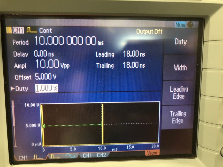 Figure 37. Arbitrary Waveform Generator Setup for Modulating Gate of Power FET
 The square wave signal was connected to test point TP29, the gate of Q1, but not activated initially. Scope probe CH-1 was placed at J7 (voltage across power resistor(s)) with rising edge trigger set, and scope probe CH-2 at J12, Vout voltage. An electronic load set to 27Amps was connected to J4 connector to set the initial current level. With the EVM powered and supplying 27Amps to e-load, the ARB signal was applied to the power MOSFET. The scope capture below shows the Vout response to the positive current step. Since the voltage across the power resistor settles at ~800mV, the current step size is estimated to be ~ 0.8V/0.02ohms = 40Amps. It is estimated that the current step is from 27Amps to 67Amps.
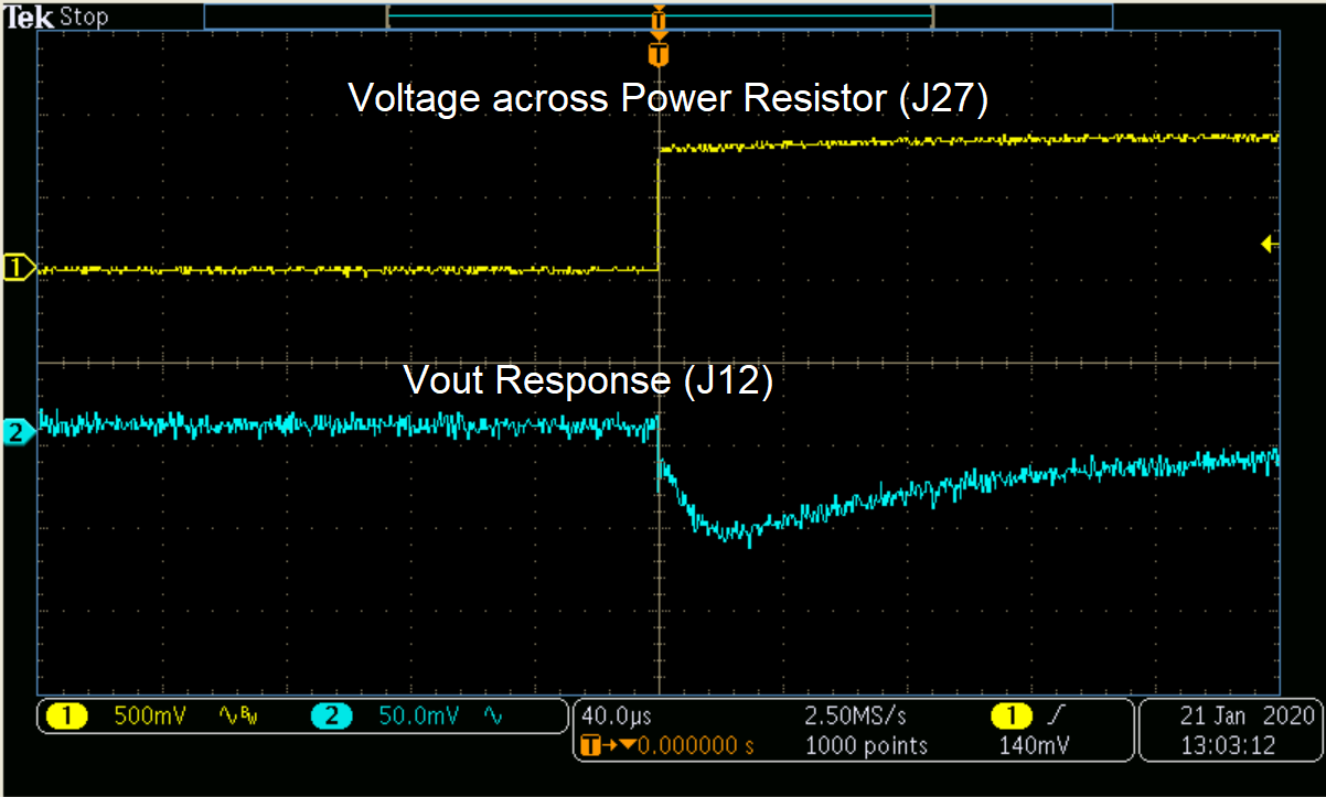 Figure 38. Vout Transient Response to Current Step from 27A to 67A
 The same is repeated for a negative current step by setting the trigger to falling edge on CH-1.
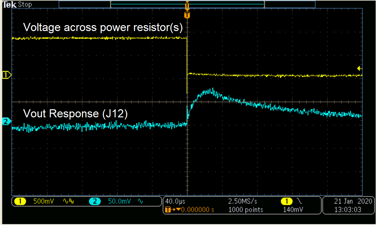 Figure 39. Vout Transient Response to Current Step from 67A to 27A
 By changing the value of the power resistor(s) and the initial current set by the e-load, any desired current step size is achievable.