SLVUBW7 May   2020


  1.   TPS7H4001QEVM-CVAL Evaluation Module User's Guide
    1.     Trademarks
    2. 1 TPS7H4001QEVM-CVAL Overview
      1. 1.1 Features
      2. 1.2 Applications
    3. 2 TPS7H4001QEVM-CVAL Default Configuration
    4. 3 TPS7H4001QEVM-CVAL Initial Setup
    5. 4 TPS7H4001QEVM-CVAL Testing
      1. 4.1 Output Voltage Regulation
      2. 4.2 Quadrature Phases
      3. 4.3 Output Voltage Ripple
      4. 4.4 Soft Startup
      5. 4.5 Transient Response to Positive/Negative Load Step (27 A to 67 A to 27 A)
      6. 4.6 Loop Frequency Response
      7. 4.7 Efficiency
      8. 4.8 Current Limiting
      9. 4.9 Current Sharing
    6. 5 TPS7H4001QEVM-CVAL EVM Schematic
    7. 6 TPS7H4001QEVM-CVAL Bill of Materials (BOM)
    8. 7 Board Layout
    9. 8 Appendix A

Efficiency

The efficiency of the 4-channel design was measured from a 0A to 72A load currents. Figure 12 shows a peak efficiency of Y% at 9A load and X% at 72A load. The measurement recordings for this test were done without instrument automation and without controlled DUT temperature. Therefore, self heating effects of the device are evident in the slight curvature of the plot.
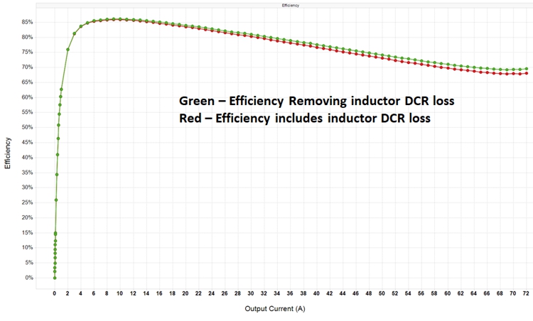
TPS7H4001QEVM-CVAL tps7h4001qevm-cval-typical-characteristic-efficiency-slvubw7.jpgFigure 12. Typical Characteristics Efficiency