SLVUBW7 May 2020
- TPS7H4001QEVM-CVAL Evaluation Module User's Guide
4.6 Loop Frequency Response
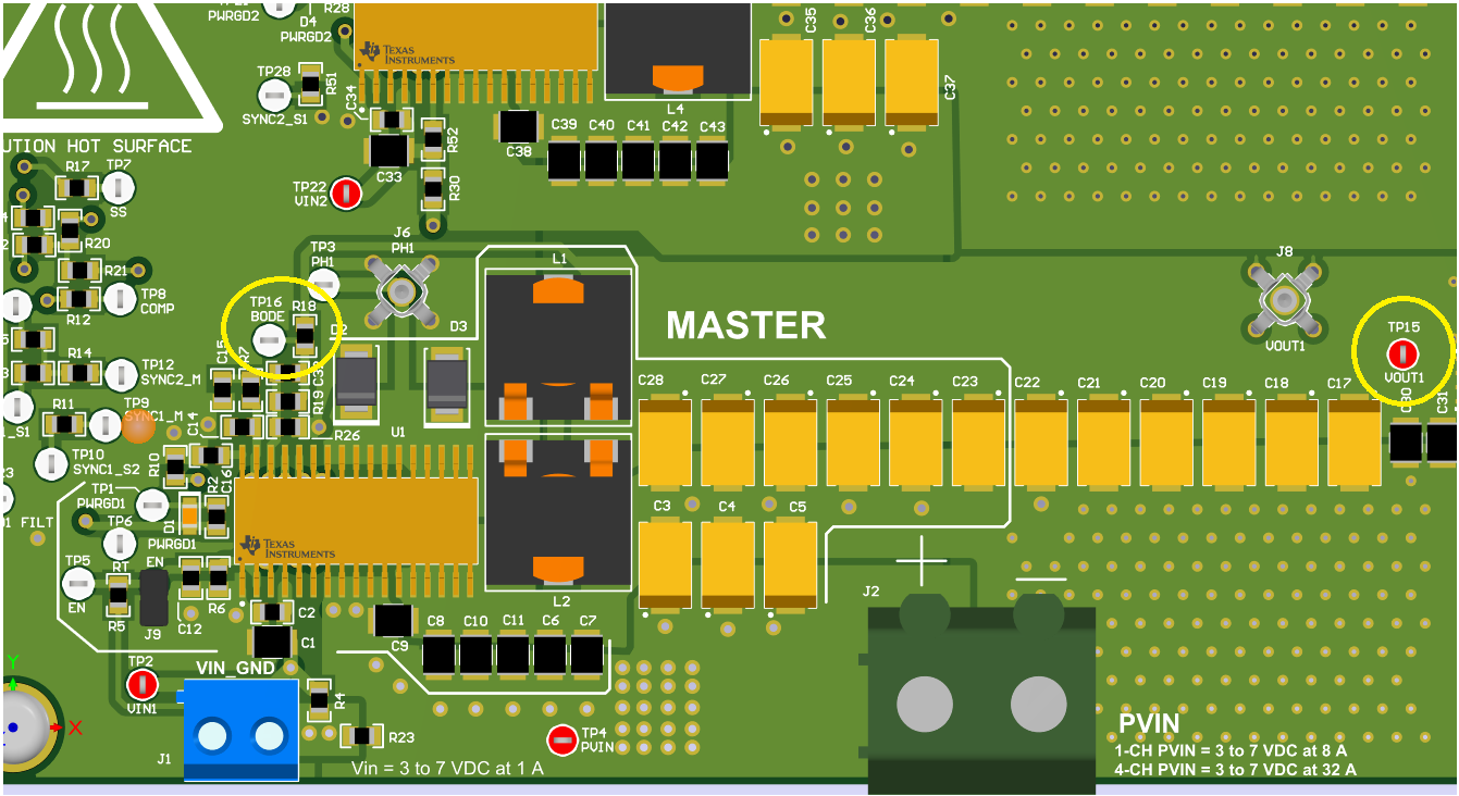
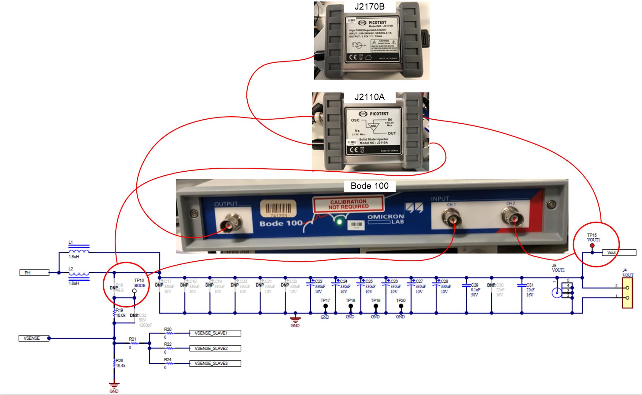
Measuring the frequency response of the feedback loop requires a unique test setup as well as physical changes to the EVM. 0-Ω resistor jumper R18, to the right of TP16 (BODE) test point and circled in yellow in the graphic below, must be lifted in order to break the loop. Both test points TP16 (BODE) and TP15 (VOUT1) will be used for connections to the Bode100 instruments.
 Figure 9. EVM Modification to Measure Frequency Response
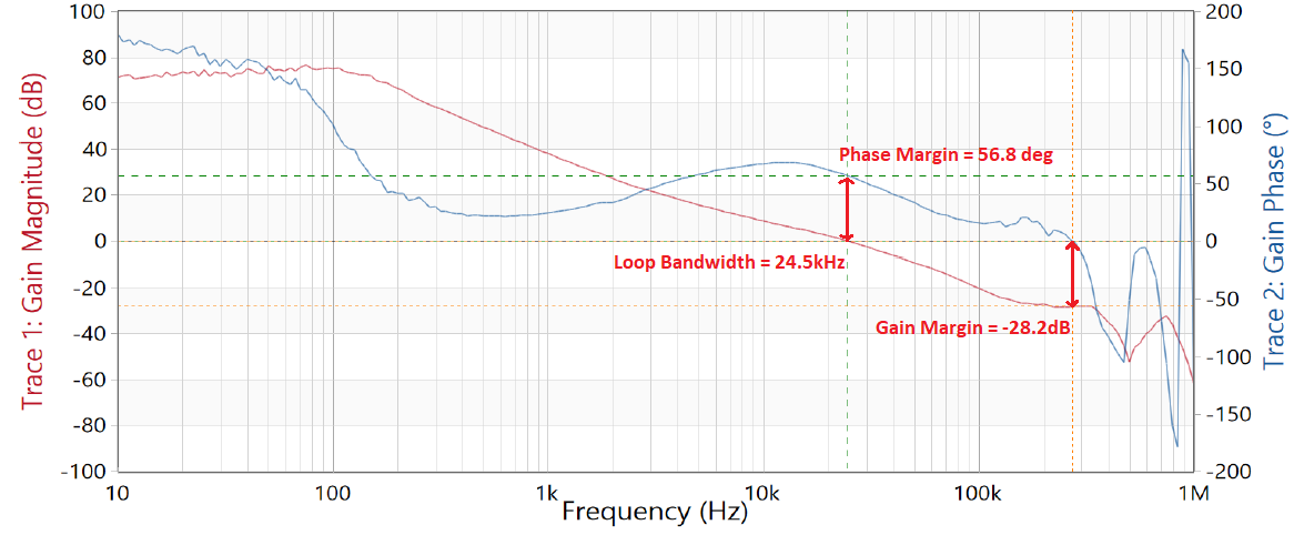
 The test setup which includes several connections to Picotest Bode100 test instruments is shown in Figure 10 with measurement results shown in Figure 11.
 Figure 10. Frequency Response Measurement Setup
  Figure 11. Loop Frequency Response (Rcomp=2kohms, Ccomp=33nF, CHF=330pF)