SLVUBX8B October 2020 – December 2021 TPS2661
- Trademarks
- 1Introduction
- 2Description
- 3Schematic
- 4General Configurations
-
5Test Setup and Procedures
- 5.1 Overload Protection Test
- 5.2 Output Short-Circuit Test
- 5.3 Input Undervoltage Protection Test
- 5.4 Output Undervoltage Protection Test
- 5.5 Output Overvoltage Protection Test
- 5.6 TPS26612 Overload Protection Test
- 5.7 Current Limiting for VIN < –Vs
- 5.8 Surge Protection Test (Current Input, CH1)
- 5.9 Surge Protection Test (Analog Output, CH2)
- 6EVAL Board Assembly Drawings and Layout Guidelines
- 7Bill Of Materials (BoM)
- 8Revision History
5.5 Output Overvoltage Protection Test
Use the following instructions to perform output overvoltage protection test:
- Set dual polarity regulated power supply to +15 V : 0 V : –15 V and apply the power at connector J2
- Connect a load of 3 kΩ between I_IN_1 and AGND_1 at connector J1
- Apply a voltage of 0 V at I_OUT_1 and gradually increase the voltage to 15.3 V to trigger the output overvoltage fault
- Observe the waveforms using an oscilloscope
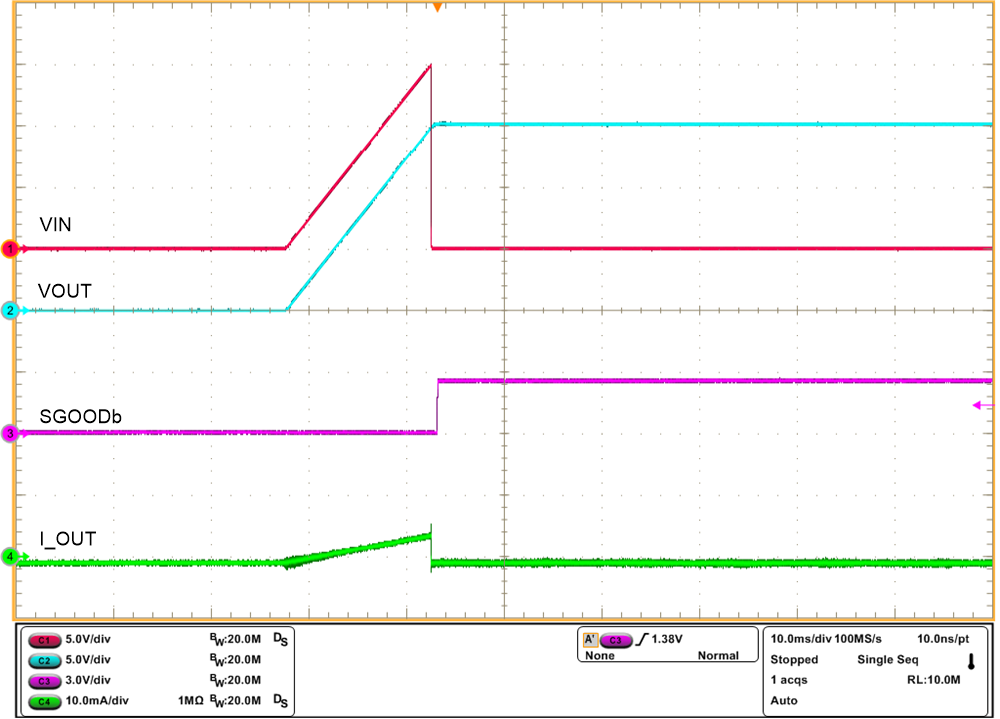
Figure 5-9 shows output overvoltage protection response of TPS26610 on TPS2661EVM eFuse evaluation board.
 Figure 5-9 Output Overvoltage Protection
Response of TPS26610 Device